
Screw compressor

Inactive Publication Date: 2008-02-14
HITACHI APPLIANCES INC
View PDF9 Cites 12 Cited by
  • Summary
  • Abstract
  • Description
  • Claims
  • Application Information

AI Technical Summary

Benefits of technology

[0014]According to the present invention, a screw compressor capable of performing an effective operation as a screw chiller can be obtained.

Problems solved by technology

Because the screw compressor in JP-A-59-211790 adopts an operating method in which the rotational speed is increased to a constant rotational speed and a capacity control valve is used in the range of 50% to 25%, there is a problem that a highly improved performance cannot be expected because of the increase in mechanical loss due to the increased speed and a bypass imposed by the capacity control valve.

Method used


Image

  • Screw compressor
  • Screw compressor
  • Screw compressor

Examples


Embodiment Construction

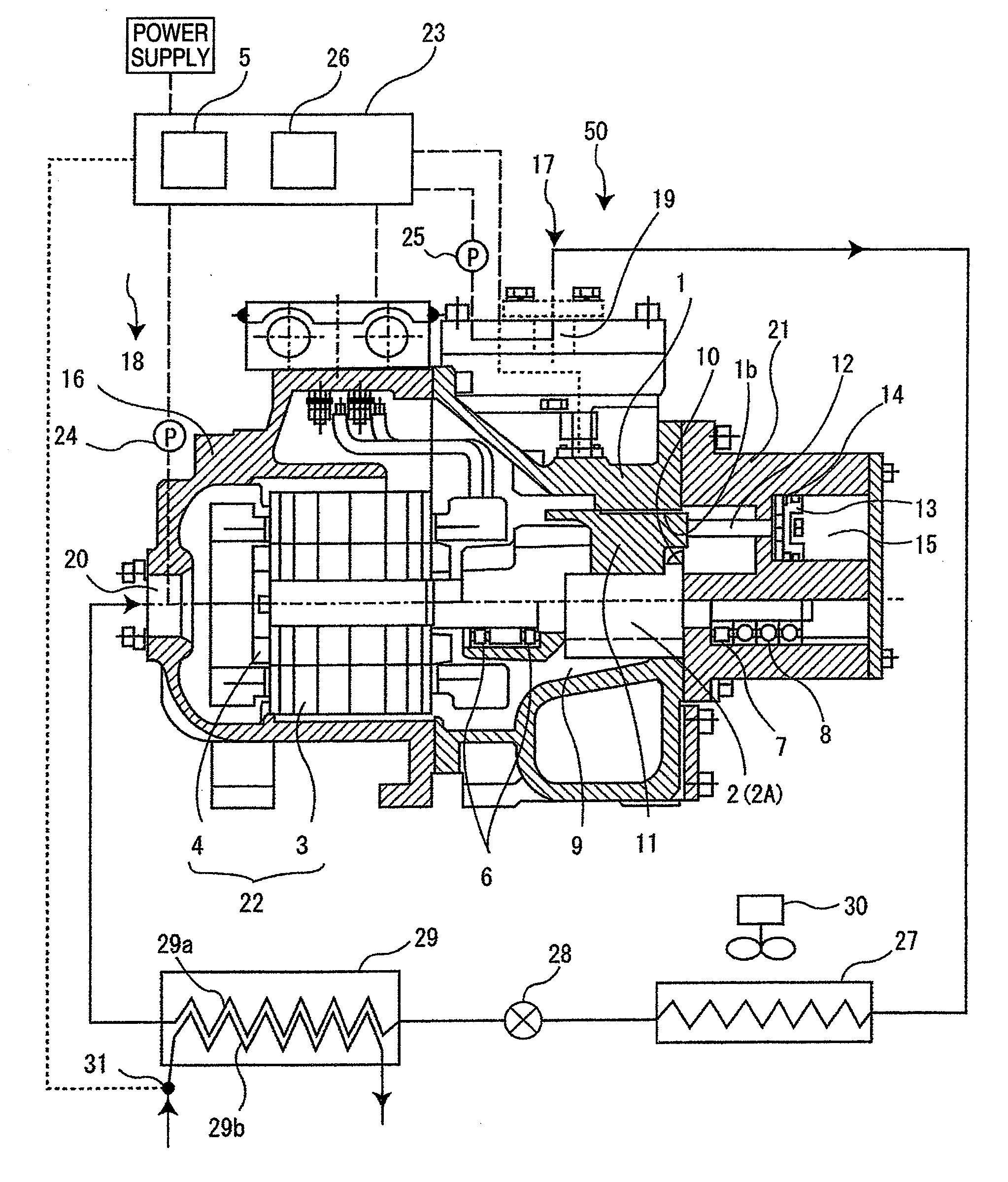
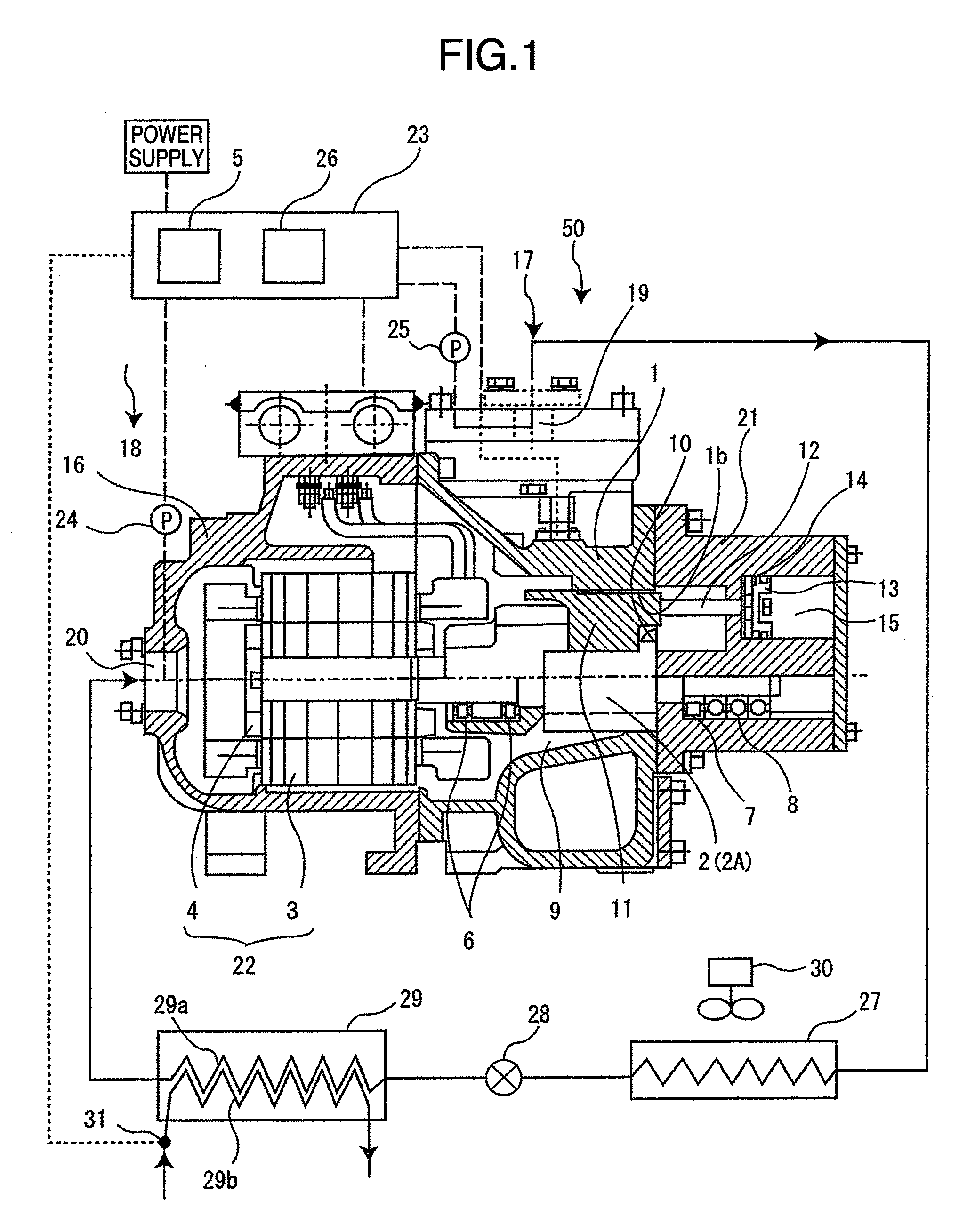
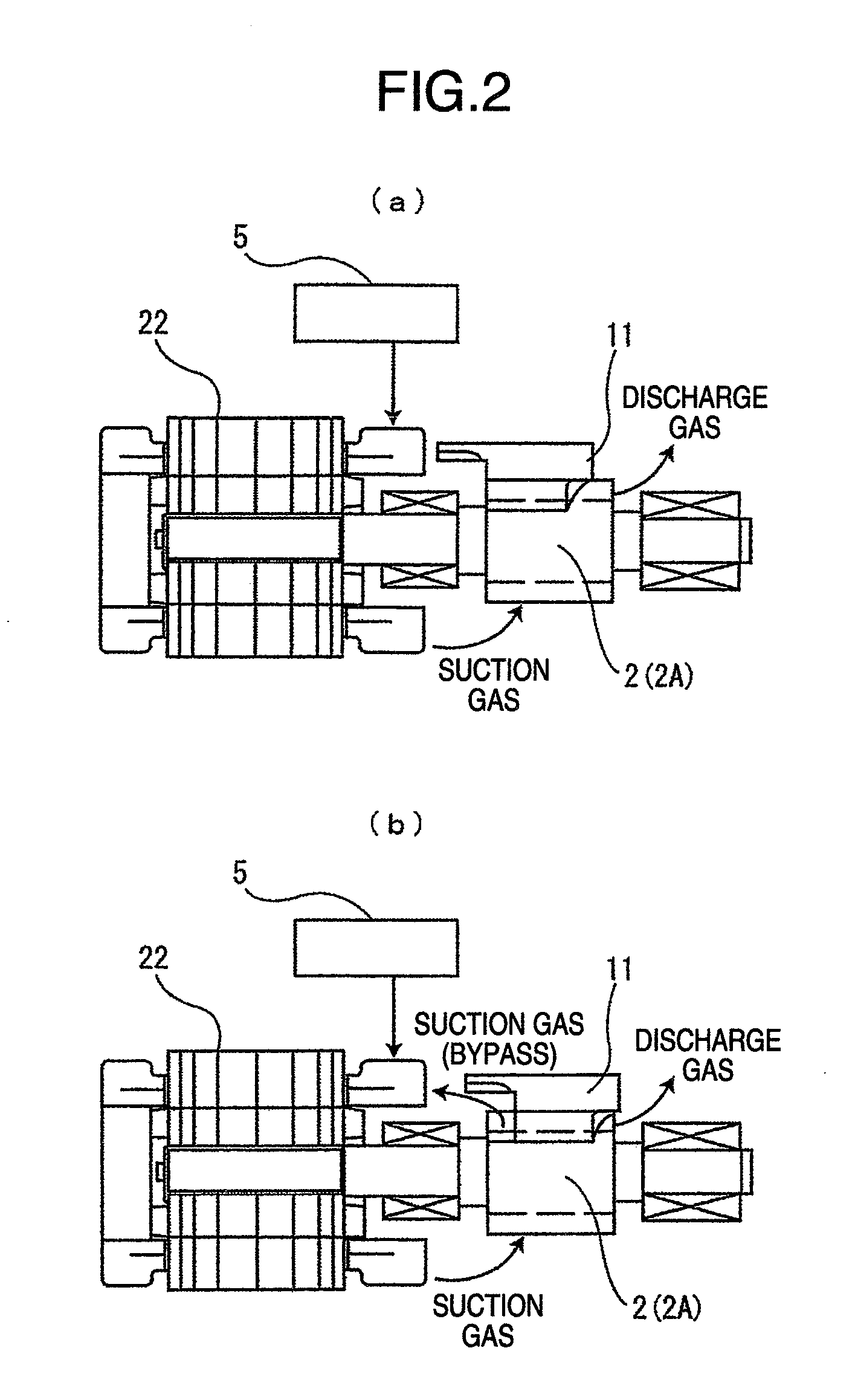
[0019]Hereinafter, one embodiment of the present invention will be described with reference to FIGS. 1 to 3. FIG. 1 is a sectional view of a screw compressor showing an embodiment of the present invention, FIG. 2 is an operation explanatory view of a capacity control valve in FIG. 1, and FIG. 3 is a view showing a characteristic curve of compressor efficiency relative to refrigerating capacity ratio in the screw compressor of FIG. 1.

[0020]A screw compressor 50 is constituted by a screw compressor for a screw chiller comprising a compressor portion 17, a motor portion 18 and a control device 23. Refrigerant gas to be compressed flows to the compressor portion 17 through the motor portion 18, and after being compressed by the compressor portion 17, is discharged outside the compressor. While the screw compressor 50 performing a capacity control operates in such a manner that the rotational speed and the position of a capacity control valve are changed so that pressure becomes constant...


PUM


Abstract

A screw compressor is for use of a screw chiller, and comprises a pair of screw rotors and a casing housing the screw rotors, a capacity control valve for varying a ratio of volume, a motor for driving the screw rotors and an inverter for varying the rotational speed of the motor. The screw compressor is controlled using rotational speed control means by the inverter and mechanical capacity control means by the capacity control valve independently or combined together according to loads. The maximum efficient point in a capacity control performed solely by the inverter is set to a rotational speed side lower than the rated operation point. In a region where the rotational speed is higher than the maximum efficient point, the inverter solely takes control from a rated rotational speed to a high rotational speed side.

Description

BACKGROUND OF THE INVENTION [0001]The present invention relates to a screw compressor, and in particular, relates to a screw compressor suitable for a screw chiller.[0002]As a screw compressor used for a conventional refrigerating apparatus, there is the one disclosed in JP-A-59-211790. A scroll wrap compressor of JP-A-59-211790 operates to vary a ratio of volume by performing an unload control with a capacity control valve (slide valve) in the capacity control range of 100% to 75% of a refrigerating capacity. Further, in the capacity control range of 75% to 37.5% of the refrigerating capacity, the scroll wrap compressor increases the rotational speed of the screw compressor by 1.5 times by an inverter, and by using the capacity control valve in the range of 50% to 25% of the refrigerating capacity, can operate to vary the ratio of volume. Such operation can provide efficiency better than when operated under a 100% load.[0003]Further, as another conventional screw compressor, there ...

Claims


Application Information

Patent Timeline
IPC IPC(8): F04B17/00
CPCF04C18/16F04C28/08F04C28/125F04C2240/403F04C2270/70F04C2270/18F04C2270/19F04C2270/42F04C2270/44F04C2240/52
Inventor YONEMOTO, RYUICHIROIIZUKA, YASUAKITOJO, KENJI
Owner HITACHI APPLIANCES INC
Learn More