
Sensory System and Method Thereof

a sensor system and sensor technology, applied in the field of machine sensory systems, can solve the problems of no effective system available or suggested for determining specifically optimized mold close time parameters, and the cost of goods is substantially increased, so as to facilitate the diagnosis determination of temperature, system adjustment in response, and optimize the effect of cycle tim

Inactive Publication Date: 2008-02-14
AVALON VISION SOLUTIONS
View PDF66 Cites 26 Cited by
  • Summary
  • Abstract
  • Description
  • Claims
  • Application Information

AI Technical Summary

Benefits of technology

[0014]Thus, a feature and advantage of the present invention is the ability of such a sensory system and method to enable optimization of cycle time by minimizing mold close time.
[0015]Another feature and advantage of the present invention is the ability of such a sensory system and method to facilitate diagnostic determination of the temperature of the center of a molded part following opening of the mold, thereby enabling system adjustment in response thereto.
[0016]Another feature and advantage of the present invention is the ability of such a sensory system and method to maximize throughput and quality realized from a machine.
[0017]Another feature and advantage of the present invention is the ability of such a sensory system and method to be incorporated with a part-forming machine to facilitate minimization of closed mold cooling time via defined parameter assessment and adaptive feedback control.
[0018]Another feature and advantage of the present invention is the ability of such a sensory system and method to incorporate infrared assessment capabilities to capture thermographic images of a molded part, to utilize the data to determine the most favorable mold close time parameters and to enable process adjustment in response thereto.
[0019]Another feature and advantage of the present invention is the ability of such a sensory system and method to facilitate incorporation of sensors within a part-forming machine mold, thereby increasing the available data input window by allowing images to be acquired during the mold-opening process.

Problems solved by technology

In extremely time sensitive automatic cycling systems such as injection molding machines, even slight delays can affect the overall efficiency of the system and result in substantial increase in the cost of goods.
No effective system is available or suggested for determination of specifically optimized mold close time parameters.

Method used

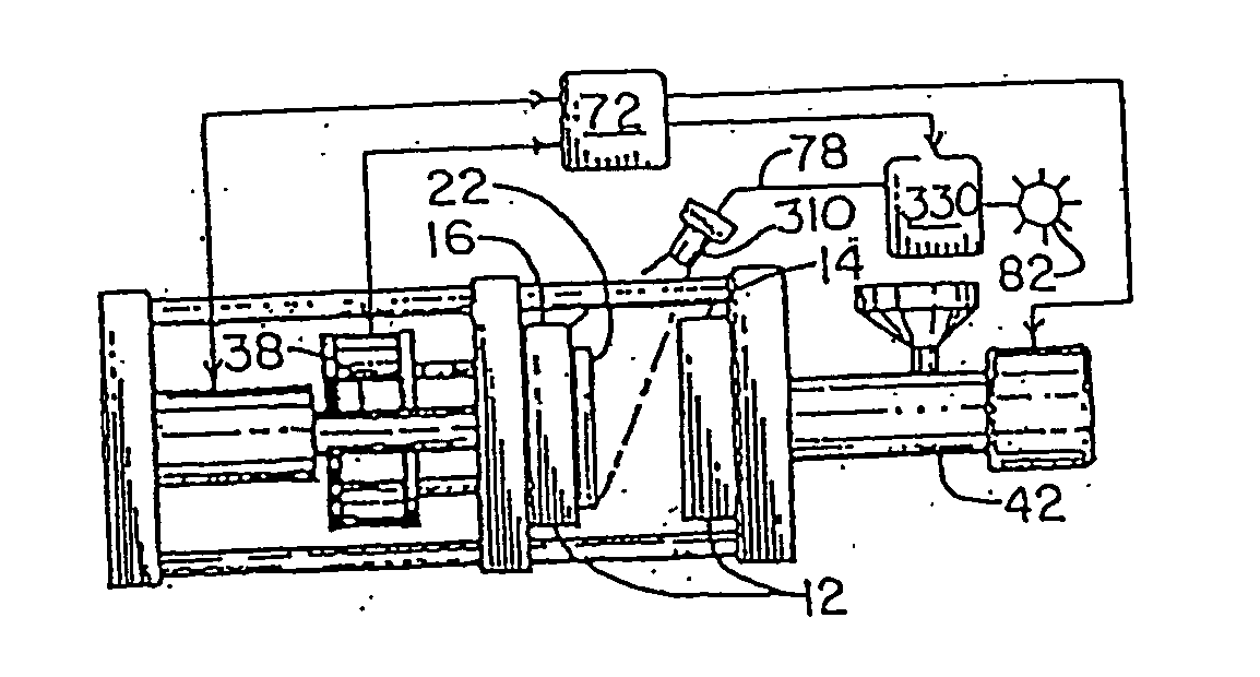
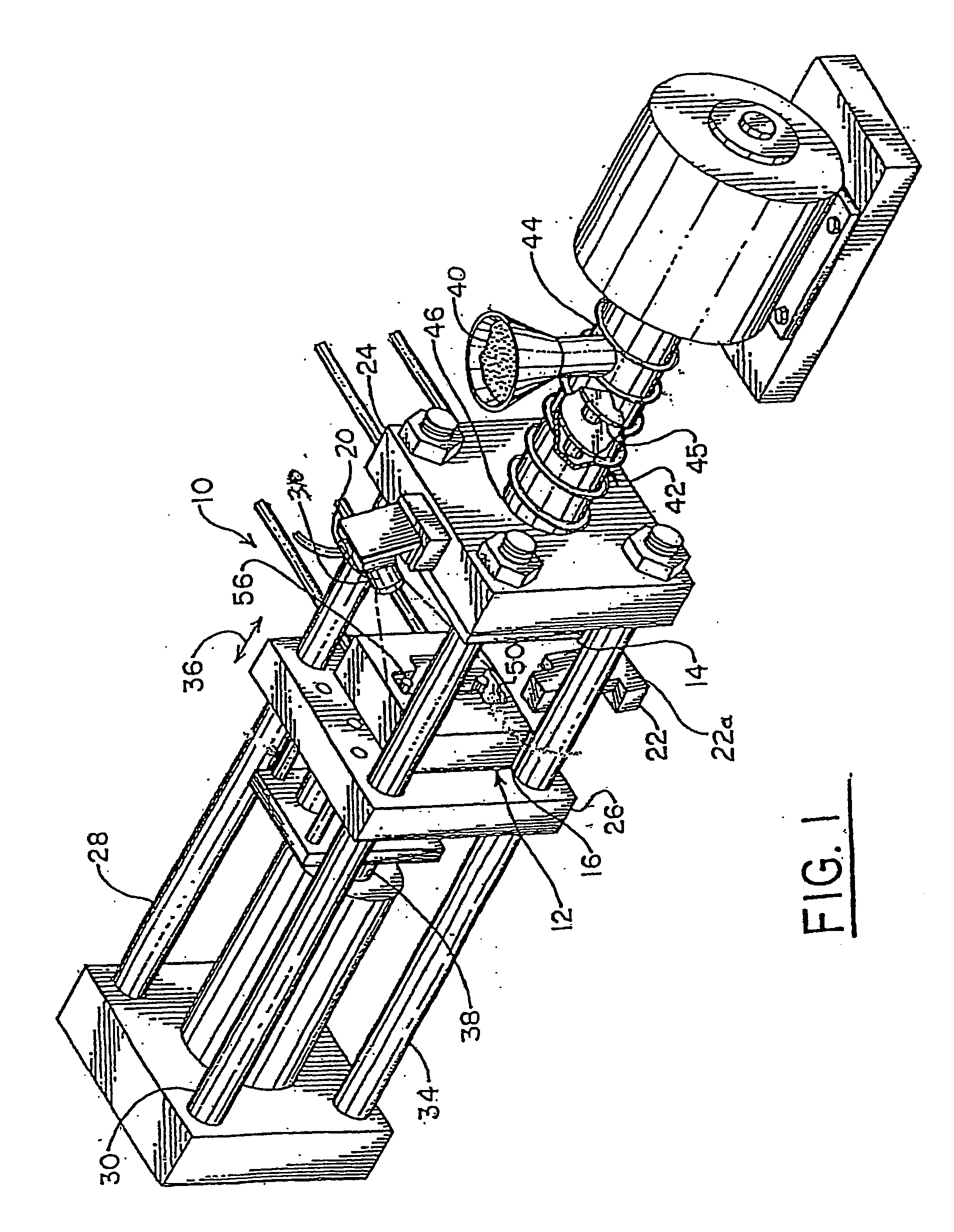
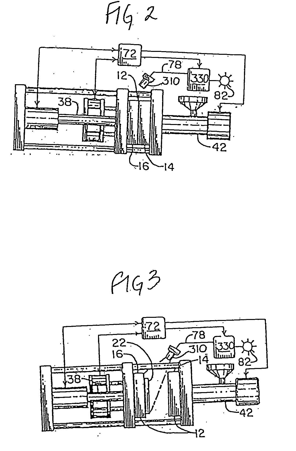

Image

  • Sensory System and Method Thereof
  • Sensory System and Method Thereof
  • Sensory System and Method Thereof

Examples


Embodiment Construction

[0032]In describing the preferred and alternate embodiments of the present invention, as illustrated in the figures and / or described herein, specific terminology is employed for the sake of clarity. The invention, however, is not intended to be limited to the specific terminology so selected; and it is to be understood that each specific element includes all technical equivalents that operate in a similar manner to accomplish similar functions.

[0033]With regard to all such embodiments as may be herein described and contemplated, it will be appreciated that optional features, including, but not limited to, aesthetically pleasing coloration and surface design, and labeling and brand marking, may be provided in association with the present invention, all without departing from the scope of the invention.

[0034]To better understand the present system and method of this invention, it will be specifically explained in the context of a particular machine system, that is, its preferred use i...


PUM

PropertyMeasurementUnit
timeaaaaaaaaaa
timeaaaaaaaaaa
timeaaaaaaaaaa

Abstract

A sensory system and method for optimizing the cycle time of a part-forming process, wherein the temperature status of a molded part is ascertained and utilized to enable minimization of mold close time.

Description

PRIORITY CLAIM AND CROSS REFERENCES[0001]The present patent cooperation treaty application claims the benefit of a U.S. provisional application entitled SENSORY SYSTEM AND METHOD THEREOF, filed Nov. 20, 2003, having assigned Ser. No. 60 / 523,779, which is a continuation-in-part application of pending non-provisional patent application, Ser. No. 10 / 619,762, filed Jul. 15, 2003, entitled SENSORY INSPECTION SYSTEM AND METHOD THEREOF, which is a continuation-in-part of pending non-provisional patent application, Ser. No. 10 / 452,698, filed Jun. 2, 2003, entitled WIRELESS IMAGE PROCESSING METHOD AND DEVICE THEREFOR, which is a continuation-in-part and, like the present application, claims the benefit of pending non-provisional patent applications, Ser. No. 09 / 644,389, filed Aug. 23, 2000, entitled PART-FORMING MACHINE CONTROLLER HAVING INTEGRATED SENSORY AND ELECTRONICS AND METHOD THEREOF, and Ser. No. 10 / 246,974, filed Sep. 19, 2002, abandoned entitled PART-FORMING MACHINE CONTROLLER HAVI...

Claims


Application Information

Patent Timeline
Patent Type & Authority Applications(United States)
IPC IPC(8): B29C47/92B29C48/92B29C45/72B29C45/76B29C45/78G01K
CPCB29C45/7626B29C45/766B29C45/78B29C2945/7604B29C47/92B29C2945/76394B29C2945/76461B29C2945/76561B29C2945/76892B29C2945/7629
Inventor NICOL, WILLIAM A.
Owner AVALON VISION SOLUTIONS
Learn More