
Thermal control coatings

a technology of thermal control and coatings, applied in the direction of superimposed coating process, natural mineral layered products, instruments, etc., can solve the problems of power consumption, weight cost, power consumption, etc., and achieve the effect of increasing the complexity of the system design, power consumption and weight cos

Active Publication Date: 2008-02-14
THE BOEING CO
View PDF2 Cites 18 Cited by
  • Summary
  • Abstract
  • Description
  • Claims
  • Application Information

AI Technical Summary

Benefits of technology

[0006]In one aspect of the invention, a thermal control coating is provided which comprises a combination of at least one thermochromic multi-layer coating and at least one solar rejection multi-layer coating.

Problems solved by technology

Mechanical louvers usually are not used in satellite thermal control due to reliability, operational limitation, and weight issues.
However, there may be power issues, weight costs, and / or increased system design complexity as the variable conductance heat assembly may require heating and cooling for its condensers to control the pipe's conductance.

Method used


Image

  • Thermal control coatings
  • Thermal control coatings
  • Thermal control coatings

Examples


Embodiment Construction

[0021]The following detailed description is of the best currently contemplated modes of carrying out the invention. The description is not to be taken in a limiting sense, but is made merely for the purpose of illustrating the general principles of the invention, since the scope of the invention is best defined by the appended claims.

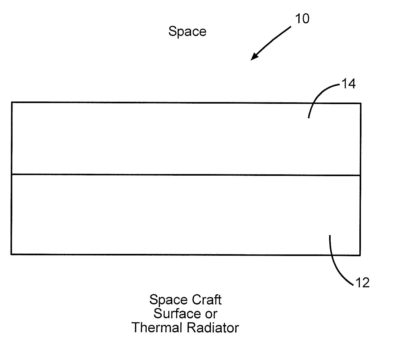
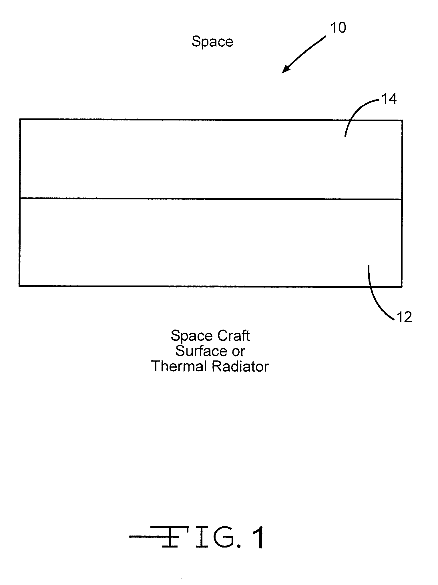
[0022]In one embodiment of the invention, as shown in FIG. 1, a thermal control coating 10 is provided. The thermal control coating 10 may cover, or be adapted to cover, one or more portions, surfaces, or components of a spacecraft. In other embodiments, the thermal control coating may be used in an assortment of other applications, such as in airplanes, and other non-aeronautical applications, such as a “sky” radiator for residential cooling. The thermal control coating 10 may be adapted to have specific thermal emittance and / or solar absorption properties at particular temperatures depending on what properties are needed for the particular application...


PUM

PropertyMeasurementUnit
transition temperatureaaaaaaaaaa
solar absorptanceaaaaaaaaaa
temperatureaaaaaaaaaa

Abstract

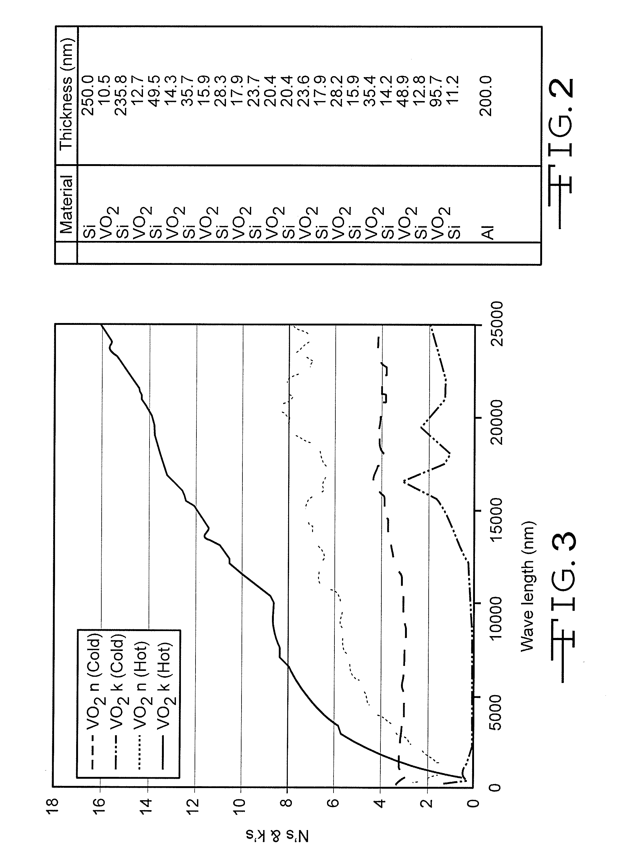
The invention discloses differing embodiments of thermal control coatings, spacecraft components having coatings, and methods for controlling the temperature of a component. In one embodiment, a thermal control coating under the invention may include one or more thermochromic multi-layer coatings and one or more solar rejection multi-layer coatings. The thermal control coating may have one or more transition temperatures at which the solar absorptance of the solar rejection coating substantially stays the same, while a thermal emittance of the thermochromic coating substantially changes.

Description

BACKGROUND OF THE INVENTION[0001]There are existing methods and devices for thermal control in one or more components of a spacecraft. Some of these methods and devices utilize heat pipes such as constant conductance heat pipe, and variable conductance heat pipe in order to maintain thermal control. Other methods and devices utilize thermal control surfaces such as mirrors, paints, coatings, and multi-layer insulation blankets. Still other methods and devices utilize heaters, mechanical louvers, and phase change materials.[0002]These thermal control tools may be grouped into local or electronic-level control, and subsystem or spacecraft-level control. For instance, phase change materials may be used at the electronic-level, and constant conductance heat pipe may be used to spread the heat of the electronics. The rest of the methods and devices referred to may be considered subsystem or spacecraft-level control.[0003]Thermal radiators made from mirrors, and thermal paints or coatings...

Claims


Application Information

Patent Timeline
Patent Type & Authority Applications(United States)
IPC IPC(8): B05D5/06B05D1/36B32B17/06
CPCC23C28/042C23C28/322C23C28/42C23C28/3455C23C28/34
Inventor KELLER, JOHN G.MOY, ROBERT M.FELLAND, JANE R.
Owner THE BOEING CO
Learn More