
Method and apparatus for treatment of bones

Inactive Publication Date: 2008-02-14
GAMBALE MICHAEL A
View PDF0 Cites 53 Cited by
  • Summary
  • Abstract
  • Description
  • Claims
  • Application Information

AI Technical Summary

Benefits of technology

[0008]A method of attaching bone in patient's body is further provided. A first plate is placed near a top surface of a bone. The first plate at least partially defines a recess, and has an opening which extends from the recess to an end wall of the first plate. A second plate is placed near a bottom surface of the bone and the bone fragment. The second plate at least partially defines a recess and has an opening which extends from the recess to an end wall of the second plate. The distal end of a screw is inserted through the opening of the first plate. The screw has an external thread convolution at the distal end and bendable sections at the proximal end. The distal end of a nut is inserted through the opening of the second plate. The nut has an internal thread convolution at the distal end and bendable sections at the proximal end. The screw is rotated to engage the external thread convolution of the screw with the internal thread convolution of the nut, wherein further rotation of the screw clamps the bone and the bone fragment between the first plate and the second plate. The bendable sections of the screw are retained against the recess of the first plate, which prevents further rotation of the screw relative to the first plate; and the bendable sections of the nut are retained against the recess of the second plate, which prevents further rotation of the nut relative to the second plate.

Problems solved by technology

However, once implanted into the patient, the devices are susceptible to vibration as the patient goes through day-to-day life.
This movement and weakened fixture impedes the ability of the body's osteoclasts to deposit new bone between the cranial flap and the skull, and thus retards healing and may ultimately render the new bone weaker and more susceptible to continued or future fracture.

Method used


Image

  • Method and apparatus for treatment of bones
  • Method and apparatus for treatment of bones
  • Method and apparatus for treatment of bones

Examples


Embodiment Construction

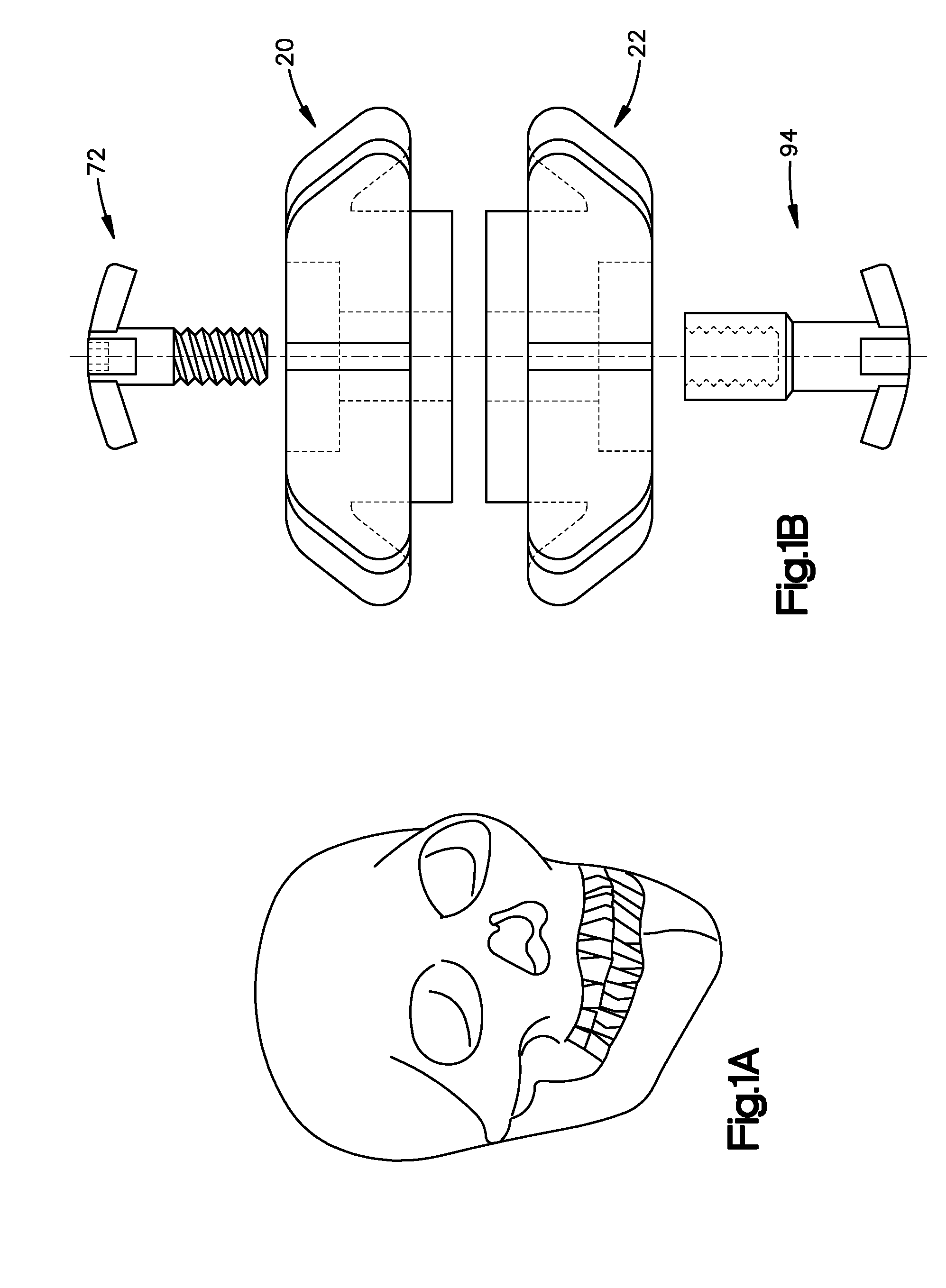
[0040]A bone disposed in a patient's body has been illustrated schematically in FIG. 1A. Although the bone illustrated in FIG. 1A is a skull 10, it should be understood that the skull is representative of many bones in a patient's body and that the present invention may be utilized in association with bones other than skull bones. As shown in the exploded view of FIG. 1B, the present invention utilizes a first plate 20, a second plate 22, a screw 72, and a nut 94 to secure the piece of bone 10 relative to another piece of bone, a skull fragment 14, to effectuate healing and bone regeneration.

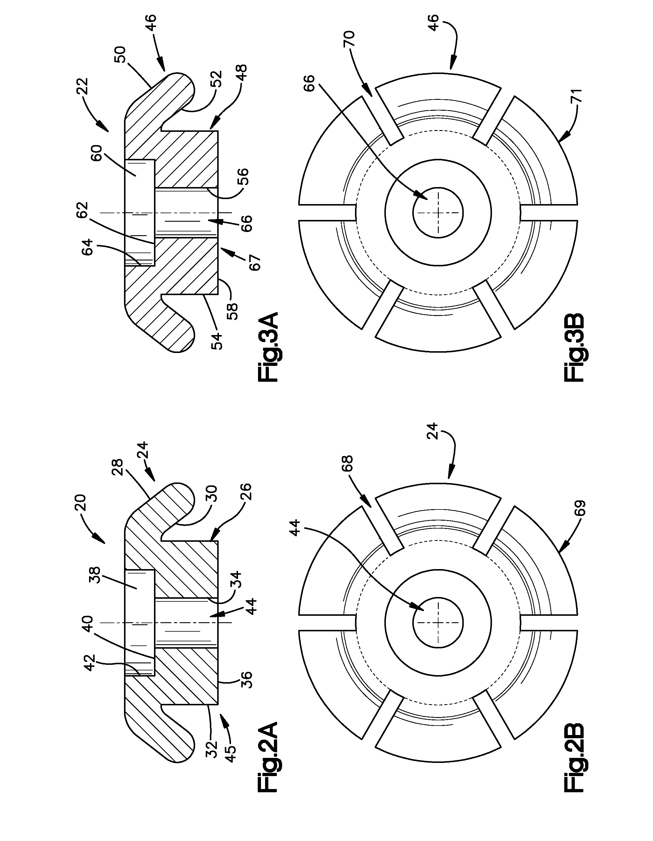
[0041]As shown in FIG. 2A, first plate 20 comprises a flange portion 24 and a trunk portion 26. The flange portion 24 and trunk portion 26 are substantially circular in nature. The flange portion 24 has a larger cross-sectional area than the trunk portion 26. In an initial condition, the flange portion 24 extends radially outward from the trunk portion 26 in a direction toward the distal end 45 ...


PUM


Abstract

An apparatus for use in attaching bone in a patient's body is provided having first and second plates, each of the plates at least partially defining a recess. A nut is also provided, having an internal thread convolution and a plurality of bendable sections. A screw is also provided, having an external thread convolution which, upon rotation of the screw, engages with the internal thread convolution of the nut; and a plurality of resiliently bendable sections. Further rotation of the screw retains both the bendable sections of the screw in the recess of the first plate and the bendable sections of the nut in the recess of the second plate, prohibiting relative movement between the screw and the first plate and the nut and the second plate and providing radial compression to the first and second plates to secure bones together.

Description

RELATED APPLICATION [0001]This application claims priority from U.S. Provisional Patent Application Ser. No. 60 / 836,802, filed on Aug. 10, 2006, the subject matter of which is incorporated herein by reference.TECHNICAL FIELD [0002]The present invention relates to a method and apparatus for treating bone and more specifically, to a method and apparatus for adjacent sections of bones.BACKGROUND OF THE INVENTION [0003]During the treatment of bones in a patient's body, it is often necessary to remove a section of the bone to access the tissue or organs underneath them. This is especially true in a craniotomy, in which a portion of the cranial vault is removed or folded back in a flap to permit surgical access to the cranial contents (such as the brain). To perform the craniotomy, several burr holes are drilled through the skull. The number and position of these holes varies depending on the shape of bone to be removed. For example, three burr holes are drilled at corner points if a tria...

Claims


Application Information

Patent Timeline
IPC IPC(8): A61B17/58A61B17/56
CPCA61B17/688A61C8/0074A61C8/005A61C8/0018
Inventor GAMBALE, MICHAEL A.
Owner GAMBALE MICHAEL A
Learn More