Expansion screw set and hollow nail and interior nail thereof

Inactive Publication Date: 2008-02-14
LEE SHIH TSENG
View PDF12 Cites 96 Cited by
  • Summary
  • Abstract
  • Description
  • Claims
  • Application Information

AI Technical Summary

Benefits of technology

[0010]The hollow structure preferably contains liquid or semisolid substances such as bone cement, marrow, artificial marrow, bone slurry or nutrient. If the interior nail is nailed into the hollow structure, the liquid or semisolid substances can be squeezed to the outside of the hollow structure through the through hole, thereby improving the fastening or treatment effect. On the other hand, if the interior nail is fully drilled into the hollow stru

Problems solved by technology

Currently, most of bone nails for medical purpose are solid structures without surface holes, and only threads on the surfaces of the bone nails are fixed into the bone, so the fastness degree of the bone nails may not be secured into the bone completely and it will depend upon the bone density.
However, the bone nails and the bone plates likely get lo

Method used


Image

  • Expansion screw set and hollow nail and interior nail thereof
  • Expansion screw set and hollow nail and interior nail thereof
  • Expansion screw set and hollow nail and interior nail thereof

Examples


Example

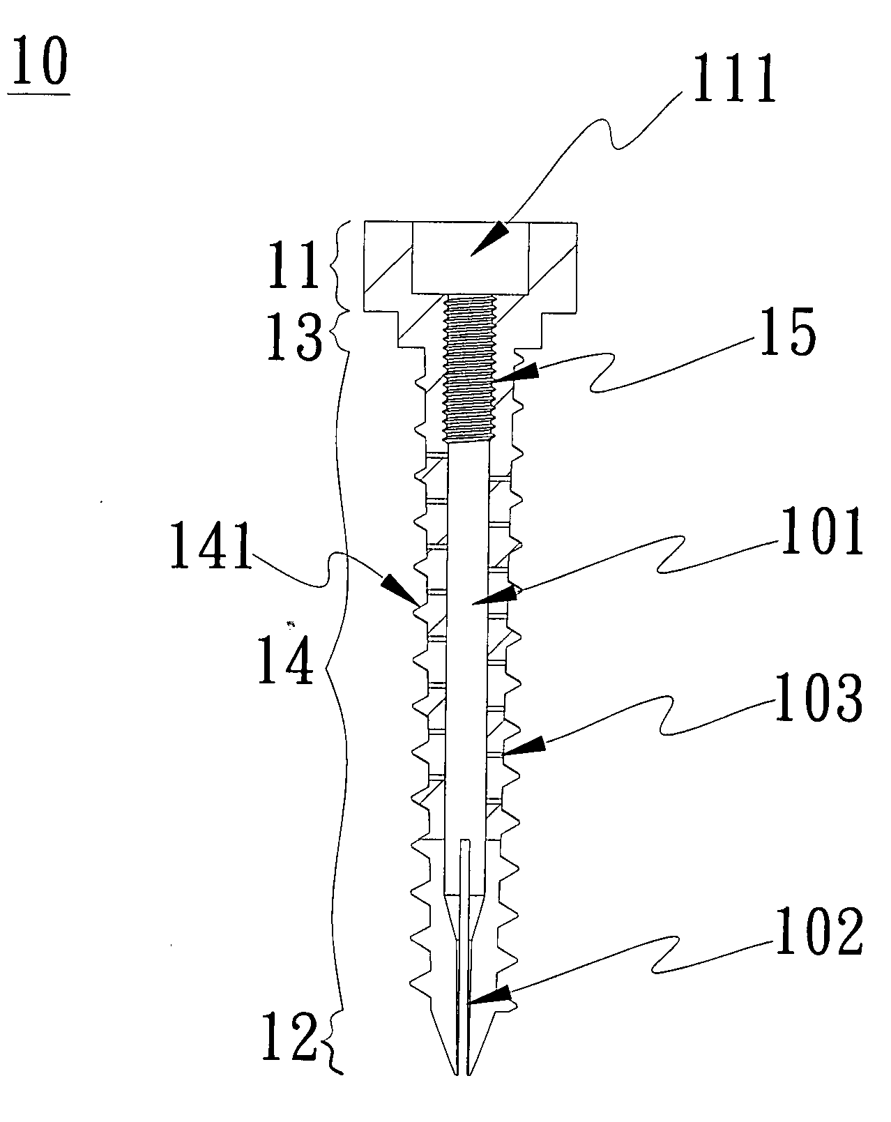
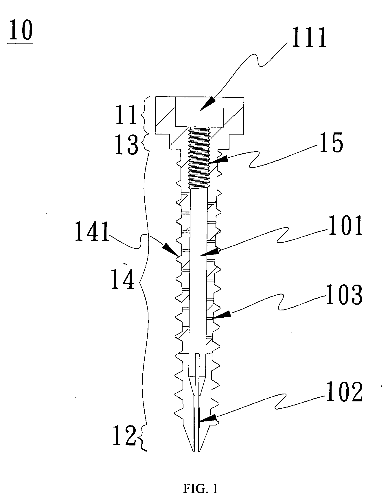
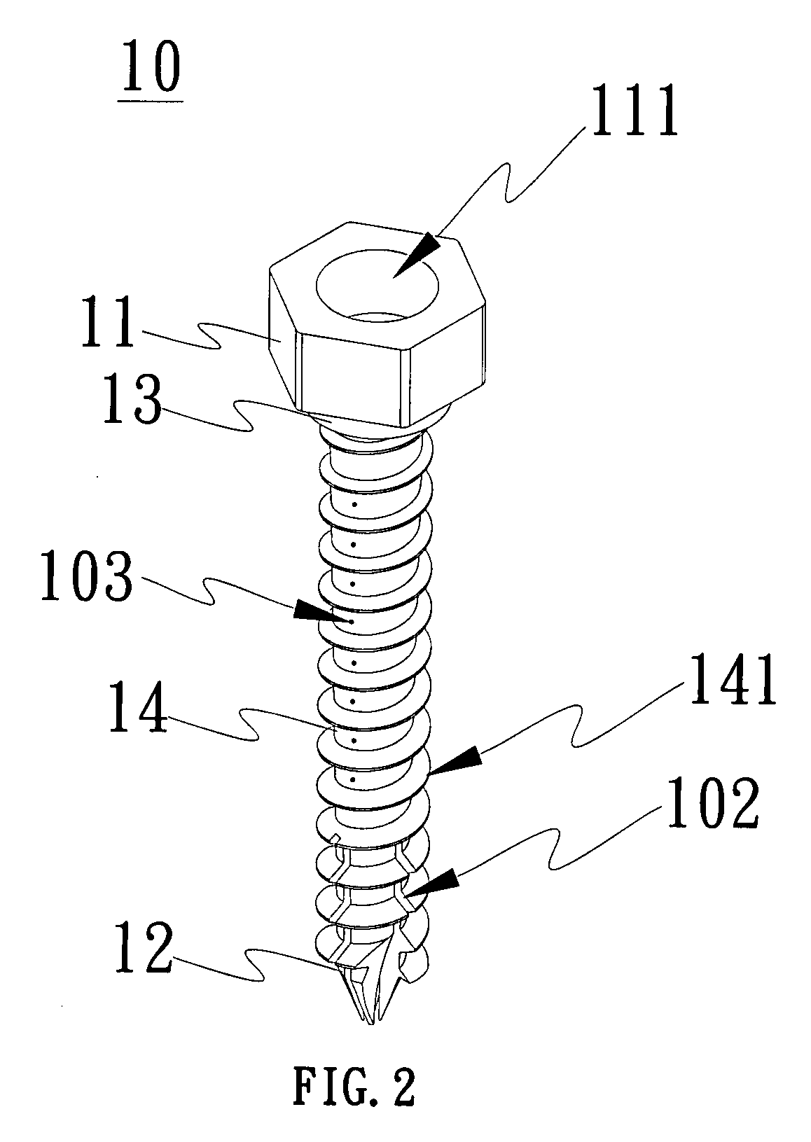
[0021]FIGS. 3 and 4 depict a cross-sectional view and a perspective view of the first embodiment of the interior nail of the present invention. The interior nail 30 comprises a nail head 31 and a nail body 32. The nail head 31 generally has a hexagonal groove 311 for rotation downwards by adding an external force. The nail body 32 has a third thread 321, and the external diameter of a lower end 322 of the nail body 32 is smaller. The nail head 31 can be accommodated within the circular groove 111 of the head 11 of the aforementioned hollow nail 10. The third thread 321 corresponds to the second thread 15 within the hollow structure 101 of the hollow nail 10, while the nail body 32 and its lower end 322 correspond to the hollow structure 101 of the hollow nail 10 so that the interior nail 30 can be securely fastened into the hollow nail 10.

[0022]FIG. 5 depicts the cross-sectional view of the first embodiment of an expansion screw set of the present invention. The expansion screw set ...

Example

[0023]FIGS. 6 and 7 depict a cross-sectional view and a perspective view of the second embodiment of the interior nail of the present invention. The interior nail 60 comprises a nail head 31 and a nail body 62. The nail head 31 generally has a hexagonal groove 311 for rotation downwards by adding an external force. The nail body 62 has a third thread 321 and a lower end 621 with a nail-like shape. The nail head 31 can be accommodated within the circular groove 111 of the head 11 of the aforementioned hollow nail 10. The third thread 321 corresponds to the second thread 15 in the hollow structure 101 of the hollow nail 10. The nail body 62 can be accommodated in the hollow structure 101, and the lower end 621 of the nail body 60 can drill into the hollow structure 101 of the nail portion 12 of the hollow nail 10 so that the interior nail 60 can be tightly fastened into the hollow nail 10.

[0024]FIG. 8 depicts the sectional view of the second embodiment of expansion screw set of the pr...


PUM


Abstract

The invention provides an expansion screw set, a hollow nail and an interior nail. The expansion screw set is composed of the hollow nail and the interior nail. The hollow nail has a hollow structure. A first thread and a second thread are provided for the inside and the outside of the hollow nail. The interior nail has a third thread. The hollow nail could nail an object through the first thread. The third thread of the interior nail corresponds to the second thread of the hollow nail. Therefore, the interior nail can be fastened into the hollow structure after the interior nail is nailed into the hollow nail. Moreover, the hollow nail has a separation line which runs parallel to the penetration direction of the hollow structure. Alternatively, the hollow nail has a plurality of penetration holes which is vertical to the penetration direction of the hollow structure. After the interior nail is nailed into the hollow structure, the separation line can be stretched out through the interior nail. Alternatively, contents within the hollow structure are squeezed to the outside from the penetration holes through the interior nail.

Description

BACKGROUND OF INVENTION[0001]1. Field of the Invention[0002]The present invention relates generally to an expansion screw set with a hollow nail and an interior nail, and more particularly to the expansion screw set that increases the fastening performance by combining the hollow nail and the interior nail.[0003]2. Description of Related Art[0004]According to commonly used fracture treatment or prevention technologies, a bone plate is nailed securely into a bone through a plurality of bone nails. Currently, most of bone nails for medical purpose are solid structures without surface holes, and only threads on the surfaces of the bone nails are fixed into the bone, so the fastness degree of the bone nails may not be secured into the bone completely and it will depend upon the bone density. However, the bone nails and the bone plates likely get loose due to weights, the increase of the bone, osteoporosis or other factors of the patients after surgical operation is completed.[0005]For t...

Claims


Application Information

Patent Timeline
IPC IPC(8): A61B17/56
CPCA61B17/686A61B17/8685A61B17/864
Inventor LEE, SHIH-TSENGCHEN, JYI-FENGWU, CHIEH-TSAIHSU, HSUN-HUILIU, NAN-CHUN
Owner LEE SHIH TSENG
Why Eureka
Try Eureka