Modular multi-wall tray retrofitable to a wheelchair
a multi-wall tray and modular technology, applied in the field of multi-wall tray, can solve the problems of increased weight of the tray, and increased difficulty for wheelchair users to hold onto the wheelchair tray during installation and removal, and achieves enhanced communication and entertainment capabilities, low weight, and enhanced rigidity of the panel
- Summary
- Abstract
- Description
- Claims
- Application Information
AI Technical Summary
Benefits of technology
Problems solved by technology
Method used
Image
Examples
embodiment 1
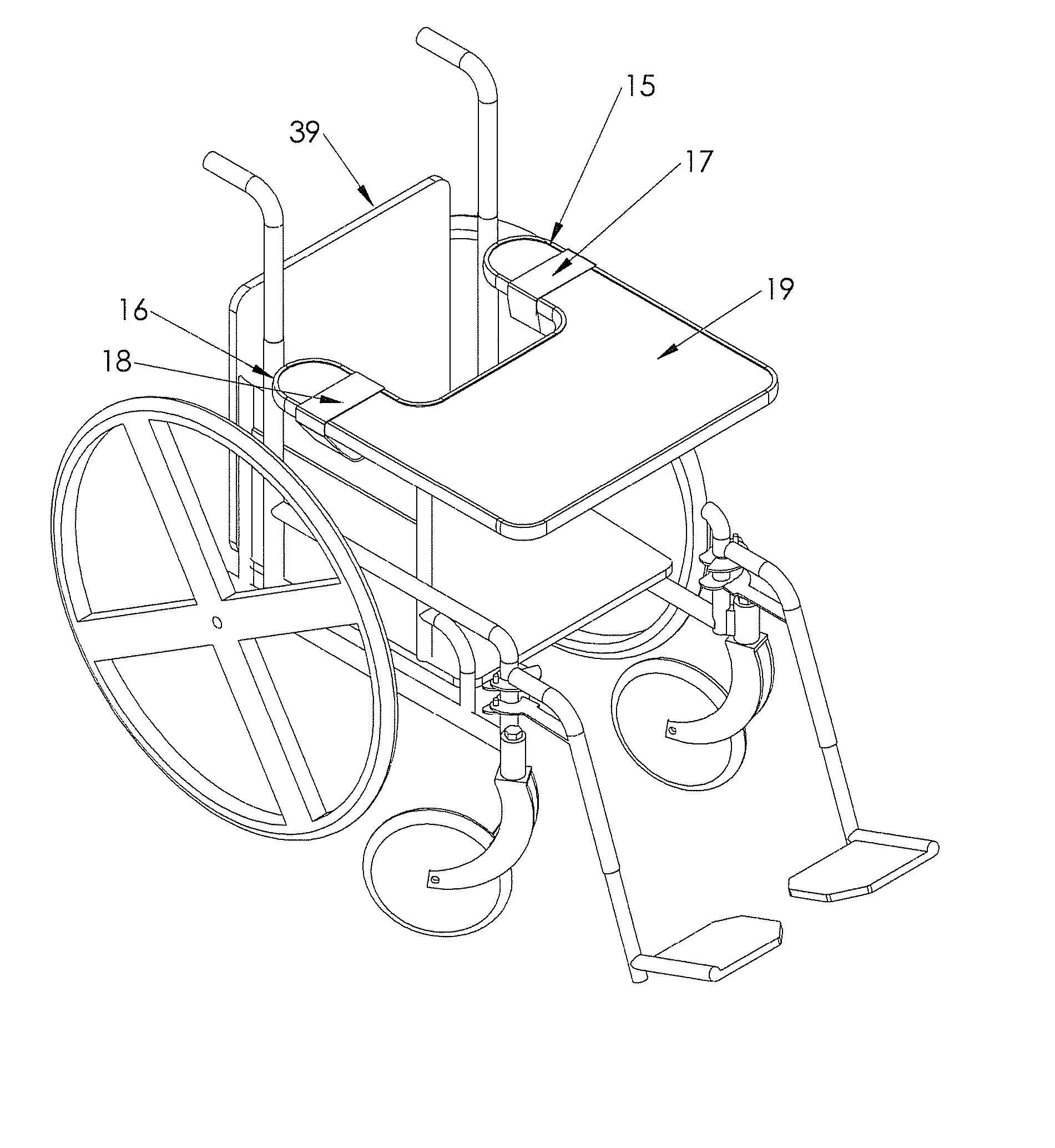
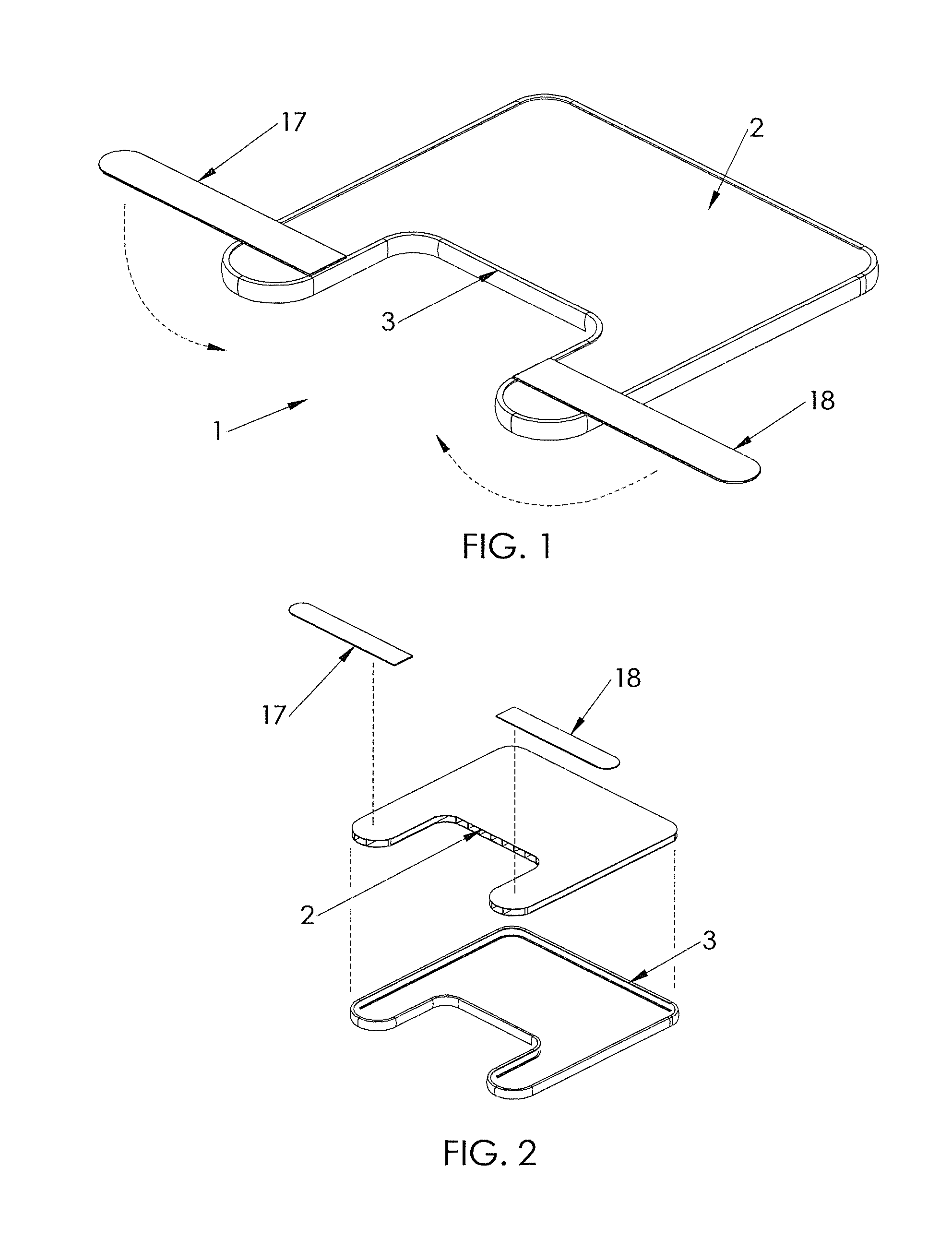
[0272] The I-Tray embodiment 1 shown in FIGS. 1 and 2 is comprised of three main elements:
[0273] 1) multi-wall tray 2
[0274] 2) edge trim molding 3
[0275] 3) double-sided Velcro® straps 17,18
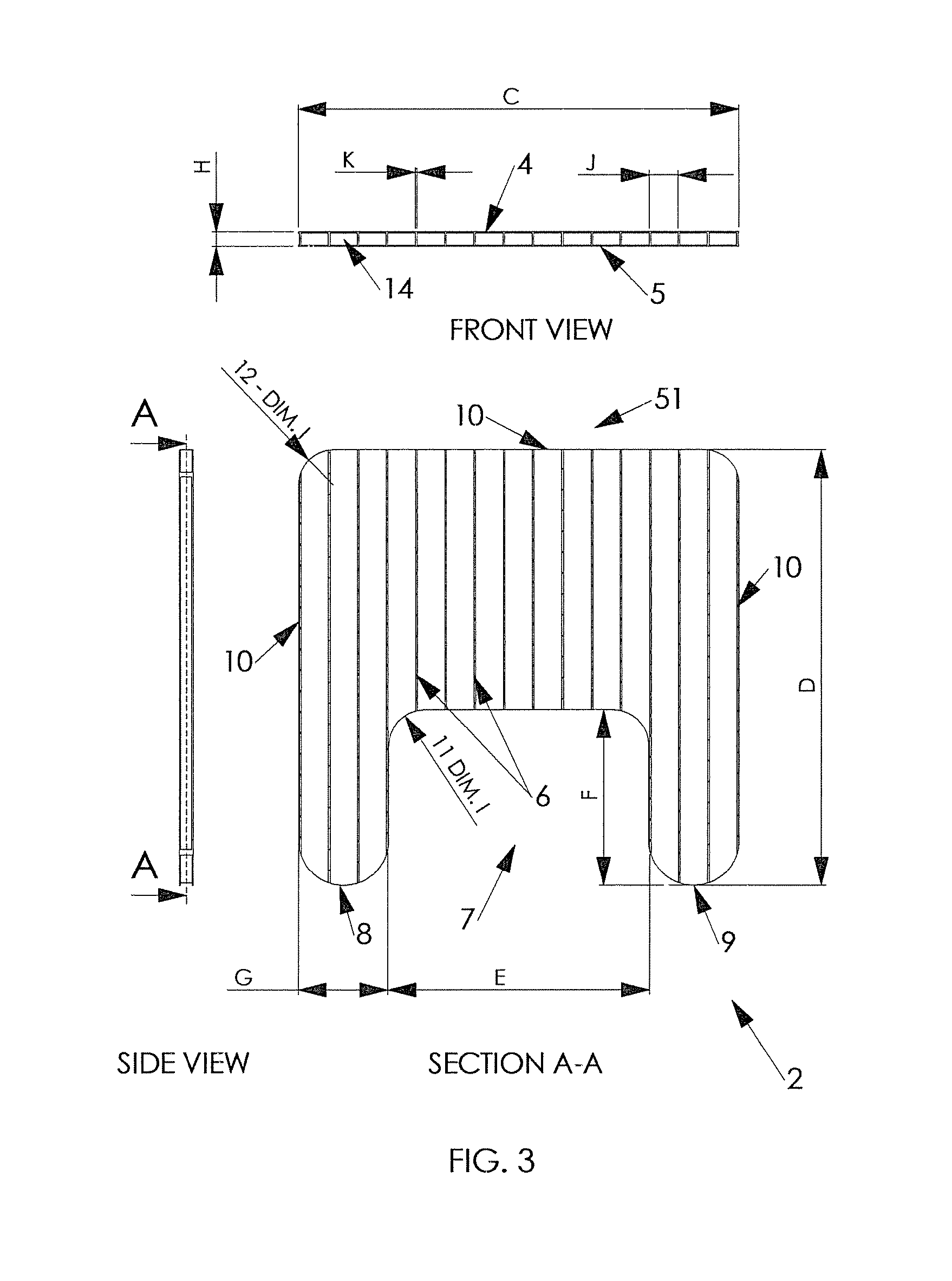
[0276] The multi-wall tray 2 shown in FIG. 3 is preferably made of a contiguous plastic or carbon fiber panel which has a) a top panel 4, b) a bottom panel 5, and c) connecting support ribs 6. As a result of this design, the multi-wall tray 2 has hollow openings 14.
[0277] The shape of the multi-wall tray 2 is defined in the layout shown in FIG. 3 and is similar to other industry-standard wheelchair trays. The multi-wall tray 2 contains a rectangular “torso” cutout 7 that contours around a wheelchair occupant's body, one left arm extension 8, and one right arm extension 9. The perimeter 10 of the multi-wall tray 2 is contoured at the corners with internal corner radii 11 and external corner radii 12 to provide comfort to the wheelchair occupant. Dimensions C, D, E, F, G, H, I, J and K are only gui...
embodiment 32
[0283] The alternative bracket mounting means embodiment 32 is comprised of five main elements shown in FIGS. 12 and 13:
[0284] 1) multi-wall tray 2
[0285] 2) screw clearance holes 33 in multi-wall tray bottom panel 5
[0286] 3) mounting inserts 34
[0287] 4) wheelchair tray mounting brackets 31
[0288] 5) screws 35
[0289] 6) optional edge trim molding 3
[0290] The mounting inserts 34 depicted in FIG. 13 are preferably made of plastic or metal, which a) are shaped and sized (preferably rectangular in cross-section) to fit into the hollow openings 14 of the multi-wall tray 2 and b) contain female receptacles 36 to accept screws 35, preferably of the flat head type. The female receptacle 36 (preferably two in quantity) in each mounting insert 34 is a simple hole with a separate internally threaded fastener 37 assembled into the female receptacle 36. Alternatively, the female receptacle 36 can be any of several conventional types, including a nut or simply a tapped hole that accepts the screw 31...
embodiment 42
[0296] The Eco-Tray embodiment 42 shown in FIGS. 15 and 16 is comprised of two main elements:
[0297] 1) multi-wall rectangular tray 43
[0298] 2) edge trim molding 3
[0299] The multi-wall rectangular tray 43 shown in FIG. 15 has a similar structure as the multi-wall tray 2 in the I-Tray embodiment 1. The multi-wall rectangular tray 43 is preferably made of a contiguous plastic or carbon fiber panel which also has a) a top panel 44, b) a bottom panel 45, and c) connecting support ribs 46. This multi-wall rectangular tray 43, similar to the multi-wall tray 2, also has hollow openings 47.
[0300] The multi-wall rectangular tray 43, as its name implies, has a generally rectangular shape. The perimeter 49 of the multi-wall rectangular tray 43 is also contoured at each of the four corners with external corner radii 48. An edge trim molding 3 can also be assembled to the perimeter 49 of the multi-wall rectangular tray 43 to complete the Eco-Tray embodiment 42.
Description of Low-Cost Eco-Tray M...
PUM
 Abstract
Description
Claims
Application Information
 - R&D
- Intellectual Property
- Life Sciences
- Materials
- Tech Scout
- Unparalleled Data Quality
- Higher Quality Content
- 60% Fewer Hallucinations
Browse by: Latest US Patents, China's latest patents, Technical Efficacy Thesaurus, Application Domain, Technology Topic, Popular Technical Reports.
© 2025 PatSnap. All rights reserved.Legal|Privacy policy|Modern Slavery Act Transparency Statement|Sitemap|About US| Contact US: help@patsnap.com


