
Gas delivery apparatus for atomic layer deposition

a technology of atomic layer and gas delivery, which is applied in the direction of chemical vapor deposition coating, transportation and packaging, coatings, etc., can solve the problems of large amount of ongoing effort and difficulty in deposition process filling submicron structures, and achieve the effect of reducing the velocity of gases

Inactive Publication Date: 2008-02-21
APPLIED MATERIALS INC
View PDF99 Cites 31 Cited by
  • Summary
  • Abstract
  • Description
  • Claims
  • Application Information

AI Technical Summary

Benefits of technology

[0011] In one aspect, the method comprises: providing one or more gases into the substrate processing chamber in an initial circular direction over a central portion of the substrate; reducing the velocity of the gases through non-adiabatic expansion; providing the gases to a central portion of the substrate; and directing the gases radially across the substrate from the central portion of the substrate to a peripheral portion of the substrate at a substantially uniform velocity.

Problems solved by technology

However, as the fringes of circuit technology are pressed, the shrinking dimensions of interconnects in VLSI and ULSI technology have placed additional demands on the processing capabilities.
Many traditional deposition processes have difficulty filling submicron structures where the aspect ratio exceeds 4:1, and particularly where the aspect ratio exceeds 10:1.
Therefore, there is a great amount of ongoing effort being directed at the formation of substantially void-free and seam-free submicron features having high aspect ratios.

Method used


Image

  • Gas delivery apparatus for atomic layer deposition
  • Gas delivery apparatus for atomic layer deposition
  • Gas delivery apparatus for atomic layer deposition

Examples


Embodiment Construction

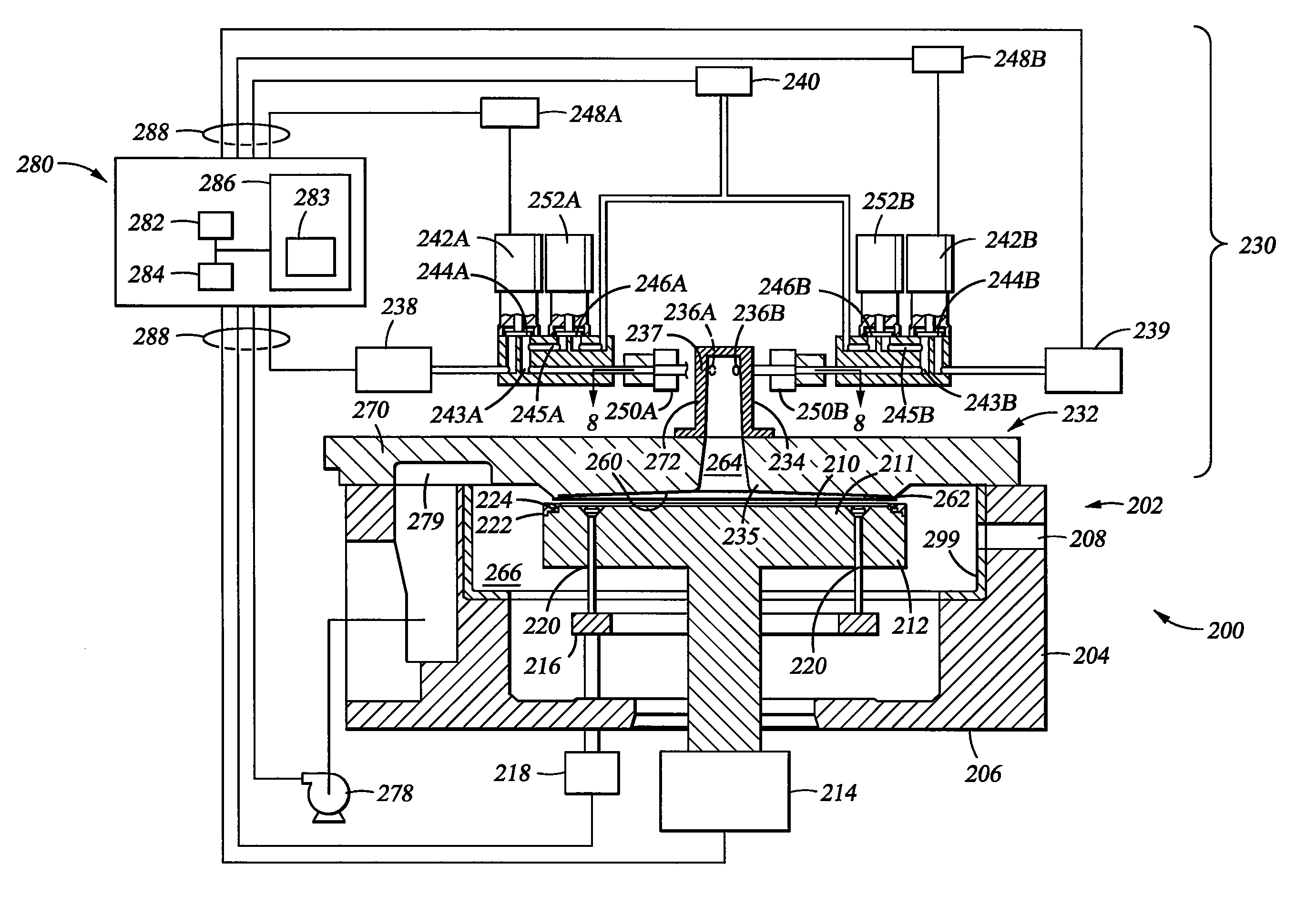
[0031]FIG. 1 is a schematic partial, cross-sectional view of an exemplary processing system 200 capable of performing cyclical layer deposition, atomic layer deposition, digital chemical vapor deposition, and rapid chemical vapor deposition techniques. The terms “cyclical layer deposition”, “atomic layer deposition”, “digital chemical vapor deposition”, and “rapid chemical vapor deposition” are used interchangeably herein and refer to gas phase deposition techniques whereby two or more compounds are sequentially introduced into a reaction zone of a processing chamber to deposit a thin layer of material on a substrate surface.

[0032] The chamber 200 includes a chamber body 202, a gas delivery system 230, a vacuum system 278, and a control unit 280. The chamber body 202 has sidewalls 204, a bottom 206, and a liner 299. A slit valve 208 is formed in a sidewall 204 of the chamber body 202 to provide access for a robot (not shown) to deliver and retrieve a substrate 210, such as a 200 mm...


PUM

PropertyMeasurementUnit
Timeaaaaaaaaaa
Angleaaaaaaaaaa
Angleaaaaaaaaaa

Abstract

Embodiments as described here provide an apparatus and a method for performing an atomic layer deposition process. In one embodiment, a deposition chamber assembly contains a substrate support having a substrate receiving surface, and a chamber lid containing a tapered passageway extending from a central portion of the chamber lid and a bottom surface extending from the passageway to a peripheral portion of the chamber lid, the bottom surface shaped and sized to substantially cover the substrate receiving surface. The system also includes one or more valves coupled to the gradually expanding channel, and one or more gas sources coupled to each valve. In one example, the gas source is an ampoule assembly which is attached to the deposition chamber by at least one disconnect fitting and contains an inlet tube directed away from the gas outlet.

Description

CROSS-REFERENCE TO RELATED APPLICATIONS [0001] This application is a continuation of U.S. Ser. No. 10 / 281,079 (APPM / 005192.P1), filed Oct. 25, 2002, which claims benefit of U.S. Ser. No. 60 / 346,086 (APPM / 005192L), filed on Oct. 26, 2001, and U.S. Ser. No. 60 / 397,230 (APPM / 005192.L2), filed on Jul. 19, 2002, and is also a continuation-in-part of U.S. Ser. No. 10 / 032,284 (APPM / 005192.02), filed on Dec. 21, 2001, and issued as U.S. Pat. No. 6,916,398, which are all herein incorporated by reference in their entirety.BACKGROUND OF THE INVENTION [0002] 1. Field of the Invention [0003] Embodiments of the invention generally relate to an apparatus and method for atomic layer deposition. More particularly, embodiments of the present invention relate to an improved gas delivery apparatus and method for atomic layer deposition. [0004] 2. Description of the Related Art [0005] Reliably producing submicron and smaller features is one of the key technologies for the next generation of very large s...

Claims


Application Information

Patent Timeline
IPC IPC(8): C23C16/00C23C16/44C23C16/455H01L21/285H01L21/768
CPCC23C16/34H01L21/76871C23C16/4411C23C16/45504C23C16/45508C23C16/45512C23C16/45525C23C16/45544C23C16/45563C23C16/45582H01L21/28562H01L21/76841H01L21/76843H01L21/76846C23C16/4404Y10T137/0396
Inventor CHEN, LINGKU, VINCENTWU, DIEN-YEHCHUNG, HUAOUYE, ALANNAKASHIMA, NORMANCHANG, MEI
Owner APPLIED MATERIALS INC
Features
  • Generate Ideas
  • Intellectual Property
  • Life Sciences
  • Materials
  • Tech Scout
  • Unparalleled Data Quality
  • Higher Quality Content
  • 60% Fewer Hallucinations
Learn More