Method for manufacturing an electric machine and electric machine manufactured according to said method

a manufacturing method and technology for electric machines, applied in the direction of stator/rotor bodies, magnetic circuit shapes/forms/construction, solid insulation, etc., can solve the problems of not sealing the cooling channel system in the end, and the sealing of the cooling channel system to the other, so as to improve cooling and heat dissipation, the effect of high mechanical strength

Inactive Publication Date: 2008-02-21
SALWIT AGRARENERGIE
View PDF5 Cites 48 Cited by
  • Summary
  • Abstract
  • Description
  • Claims
  • Application Information

AI Technical Summary

Benefits of technology

[0008] The electric machine according to the invention fulfills all requirements placed on such a machine, namely high mechanical strength, in particular also vibration strength and impact strength, complete electric insulation from the surrounding area, complete electric insulation of the machine mounts, complete electric insulation of the drive shaft, explosion protection for operation in environments with hazardous substances, increased and significantly improved cooling and heat dissipation for higher power density, integration of the power and control electronics in the housing of the machine.

Problems solved by technology

A disadvantage of this method is that the can, i.e. the wall section or can closing the machine element on its gap surface in the area of the grooves is connected insufficiently with the inner surface of the plate packet enclosing the rotor, thus resulting after a short period of operation in loosening of the can from the plate packet and subsequent damage to the can by the rotating rotor, so that the cooling channel system in the end is no longer sealed.
There are also problems with respect to the sealing of the cooling channel system to other elements of the stator or of the stator housing.

Method used


Image

  • Method for manufacturing an electric machine and electric machine manufactured according to said method
  • Method for manufacturing an electric machine and electric machine manufactured according to said method
  • Method for manufacturing an electric machine and electric machine manufactured according to said method

Examples


Embodiment Construction

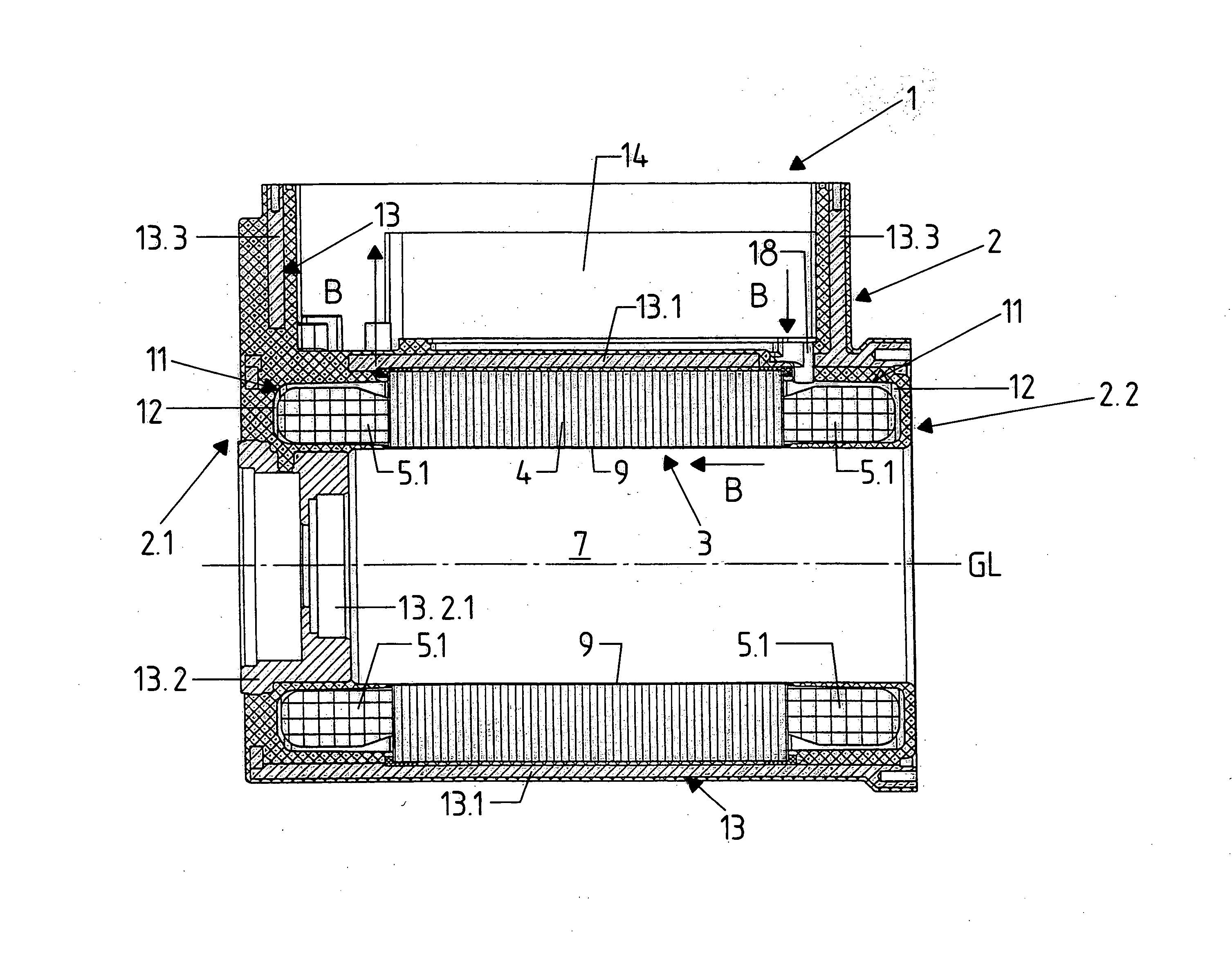
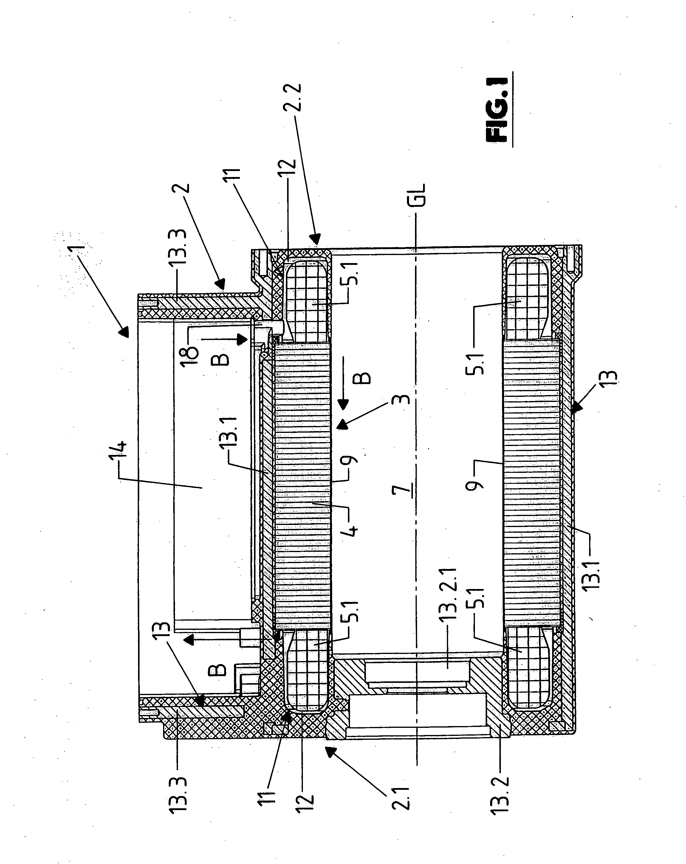
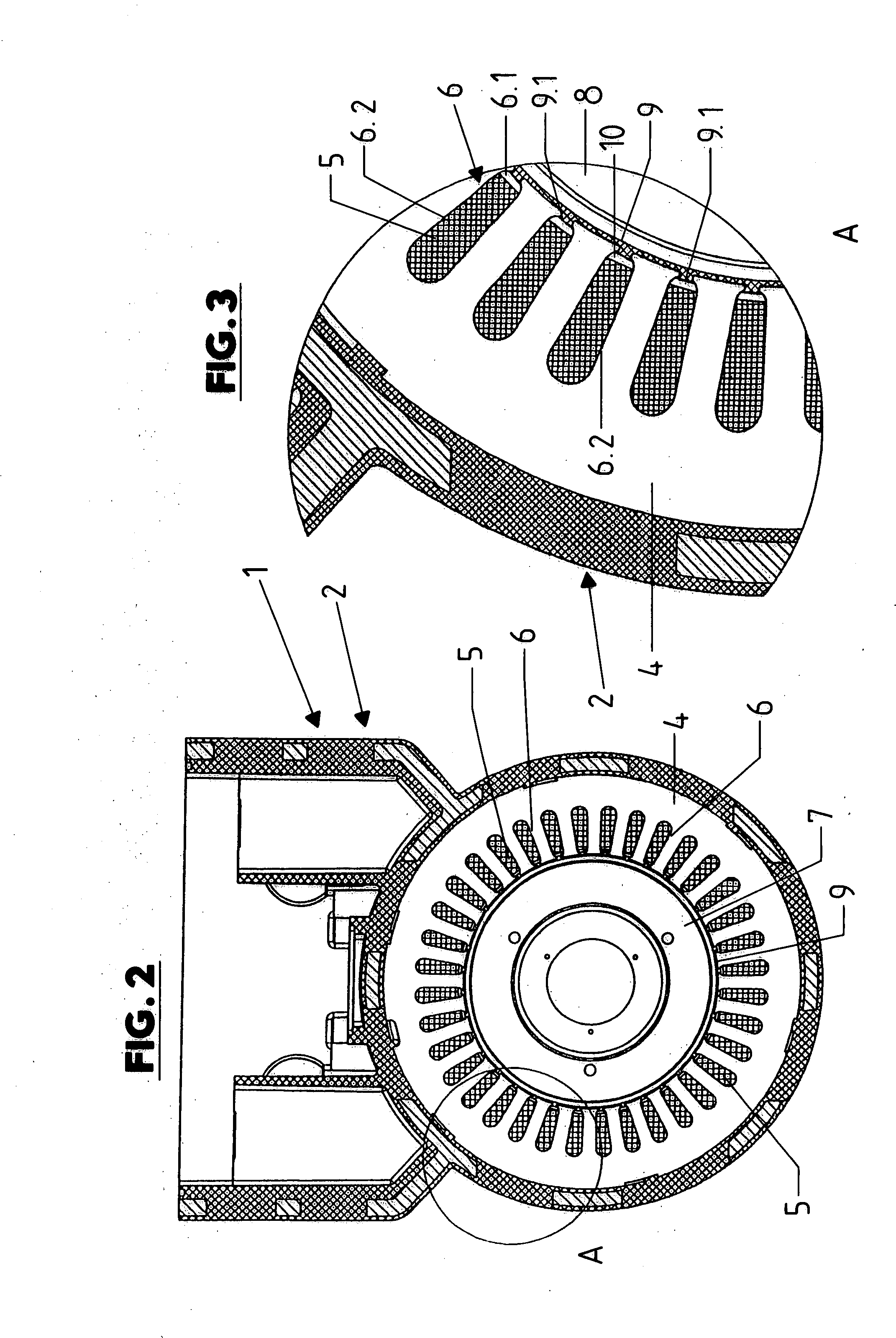
[0021] The high-power electric motor generally designated 1 in FIGS. 1-9 has an external motor housing 2 and of the stator 3 located concentrically around a housing longitudinal axis GL. The stator 3 is formed essentially by a plate packet 4 (bundle of laminations or armature) and a coil 5, the conductors or coil sections of which occupy grooves 6 that are open toward the axis GL and extend parallel to said axis. The grooves 6 are designed so that they are open toward the space 7 enclosed by the stator 3 and serving to accommodate the rotor 8 through a slot 6.1 extending over the entire length of the plate packet 4 parallel to the axis GL, which (slot) has a considerably reduced width as compared to the remaining area 6.2 of each groove 6. The coil 5 forms coil ends 5.1 on both ends of the plate packet 4 and protruding past said ends.

[0022] The inner surface of the plate packet 4 facing the space 7 or the gap between the plate packet 4 and a second machine element, the rotor 8 is e...


PUM

PropertyMeasurementUnit
areaaaaaaaaaaa
groove widthaaaaaaaaaa
widthaaaaaaaaaa

Abstract

A method for manufacturing a machine element of an electric machine, with a plurality of magnetic poles distributed around a machine axis and with at least one coil, having several conductors distributed around the machine axis and each of which is located in a groove, wherein the machine element forms a gap surface enclosing the machine axis, on which (gap surface) when the machine is mounted it adjoins a second machine element via a machine gap and is made of a plastic, and wherein at least in the recesses for the conductors, channel sections are formed through which a coolant can circulate.

Description

BACKGROUND OF THE INVENTION [0001] The invention relates to a method for manufacturing a machine element of an electric machine with a plurality of magnetic poles distributed around a machine axis and with at least one coil. [0002] To increase the performance of an electric or electrodynamic machine, the method is known in the art of providing a so-called can on the inner surface, facing the rotor, of a stator enclosing the rotor or on the inner surface of the stator plate packet, i.e. a cylindrical wall section which seals the grooves formed in the plate packet that are open toward the rotor for accommodating the sections or conductors of the stator coil, to the machine gap between the stator and rotor. The part of each groove not occupied by the electrical conductors of the coil can then be used as a channel of a cooling channel system, through which a suitable, electrically non-conductive coolant (DE 10 2004 013 721.8) circulates. [0003] A disadvantage of this method is that the ...

Claims


Application Information

Patent Timeline
Patent Type & Authority Applications(United States)
IPC IPC(8): H02K15/02H02K1/04H02K15/12
CPCH02K1/20H02K5/128Y10T29/49012H02K15/12Y10T29/49009H02K9/19H02K9/197
Inventor BEER, ALEXANDER
Owner SALWIT AGRARENERGIE
Why Eureka
Try Eureka