Discharge-lamp lighting apparatus

a technology of lighting apparatus and discharge lamp, which is applied in the direction of electric variable regulation, process and machine control, instruments, etc., and can solve problems such as deterioration of efficiency

Inactive Publication Date: 2008-02-21
SANKEN ELECTRIC CO LTD
View PDF4 Cites 4 Cited by
  • Summary
  • Abstract
  • Description
  • Claims
  • Application Information

AI Technical Summary

Benefits of technology

[0016]According to the present invention, a discharge-lamp lighting apparatus capable of preventing a p-type FET from breaking even if an input voltage suddenly varies and securing high efficiency for a wide range of input voltage variations can be provided.

Problems solved by technology

If the input voltage Vin is low, a gate voltage to the p-type FET will be insufficient to turn on / off the p-type FET, or will increase ON-resistance to produce heat.
If the input voltage Vin is high, the gate-source voltage of the p-type FET will increase to reactively charge and discharge a capacitance between the gate and source of the p-type FET, thereby deteriorating efficiency.

Method used


Image

  • Discharge-lamp lighting apparatus
  • Discharge-lamp lighting apparatus
  • Discharge-lamp lighting apparatus

Examples


first embodiment

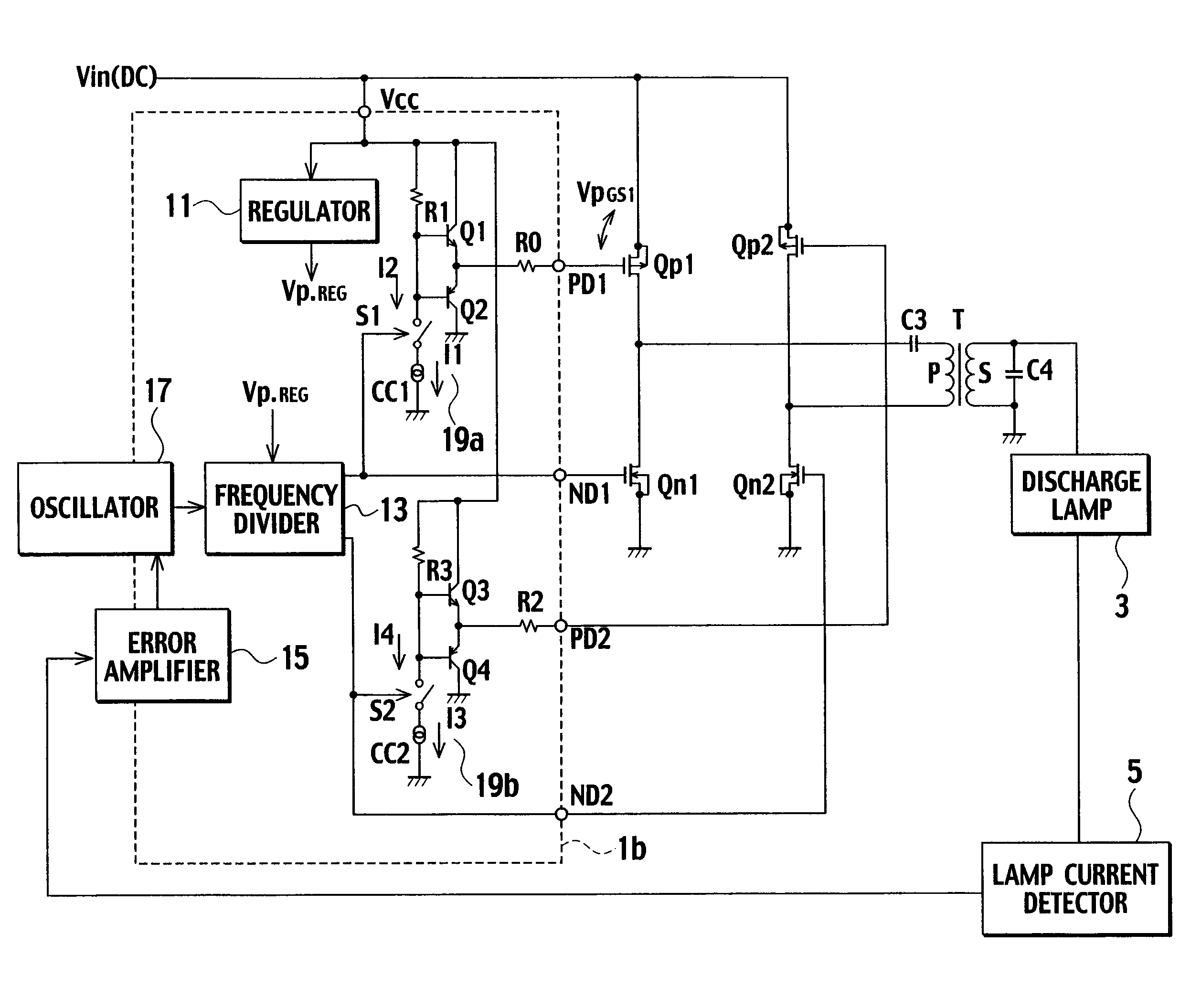
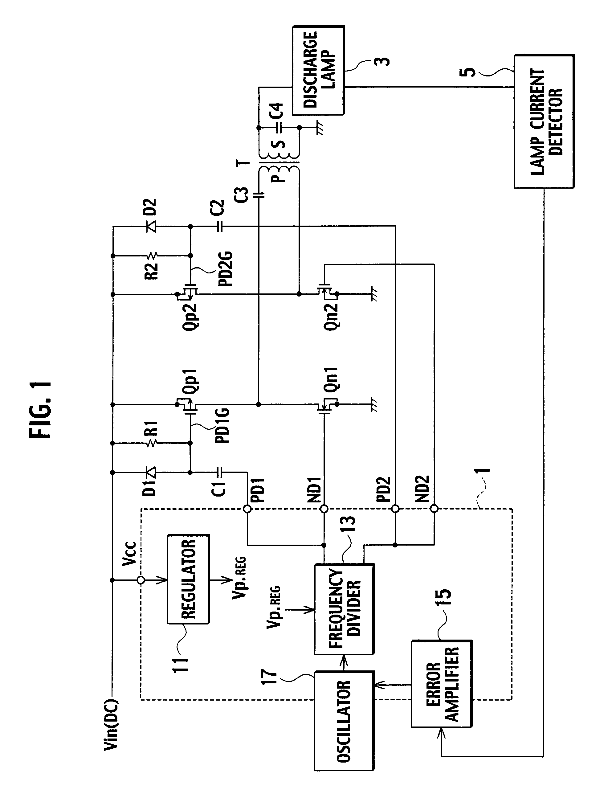
[0028]FIG. 5 is a circuit diagram showing a discharge-lamp lighting apparatus according to the first embodiment of the present invention. In the embodiment of FIG. 5, with respect to the apparatus of FIG. 1, the resistor R1, diode D1, and capacitor C1 connected to the p-type FET Qp1 of FIG. 1 are removed, and also the resistor R2, diode D2, and capacitor C2 connected to the p-type FET Qp2 of FIG. 1 are removed. In addition, the embodiment of FIG. 5 employs drive circuits 19a and 19b in a control IC 1b. The other parts of the embodiment of FIG. 5 are the same as those of the related art of FIG. 1, and therefore, are represented with the same reference marks to omit their explanations. The parts that are different from those of the related art will be explained.

[0029]The drive circuit 19a drives a p-type FET Qp1. The drive circuit 19a includes (i) a transistor Q1 configured to discharge a gate-source capacitance of the p-type FET Qp1 to turn off the p-type FET Qp1 as being turned on, ...

second embodiment

[0044]FIG. 7 is a circuit diagram showing a discharge-lamp lighting apparatus according to the second embodiment of the present invention. Unlike the first embodiment shown in FIG. 5 that employs a full-bridge architecture, the second embodiment shown in FIG. 7 employs a half-bridge architecture. In the second embodiment, with respect to the apparatus of FIG. 5, the p-type FET Qp2 and n-type FET Qn2 of FIG. 5 is replaced with capacitors C11 and C12, respectively, and the drive circuit 19b of FIG. 5 is removed. Only the operation of the drive circuit 19a for driving the p-type FET Qp1 and n-type FET Qn1 of the first embodiment of FIGS. 5 and 6 is applicable to the second embodiment of FIG. 7. Namely, the operation of a drive circuit 19a of the second embodiment shown in FIG. 7 is the same as that of the first embodiment shown in FIG. 5. The half-bridge architecture of the second embodiment is simple.

[0045]According to the second embodiment, an end of a primary winding P of a transfor...


PUM


Abstract

A discharge-lamp lighting apparatus includes series circuits connected to each end of a DC power source, a transformer, FETs Qp1, Qn1, Qp2, and Qn2, and a drive circuit. The drive circuit includes transistors Q1 and Q3 to discharge gate-source capacitances of the Qp1 and Qp2, resistance elements to determine gate potentials of the transistors Q1 and Q3 when the transistors Q1 and Q3 are turned on, transistors Q2 and Q4 to charge the gate-source capacitances of the Qp1 and Qp2, constant current circuits, and switches connected in series with the series circuits of the constant current circuits and resistance elements, respectively, to turn on/off the constant current circuits.

Description

BACKGROUND OF THE INVENTION[0001]1. Field of the Invention[0002]The present invention relates to a discharge-lamp lighting apparatus for lighting a discharge lamp, and particularly, to a discharge-lamp lighting apparatus for lighting a cold cathode lamp installed in, for example, a liquid-crystal portable device.[0003]2. Description of the Related Art[0004]Discharge-lamp lighting apparatuses are classified into those employing n-type MOSFETs as high-side switching elements and those employing p-type MOSFETs as high-side switching elements. Liquid-crystal portable devices such as notebook computers employing cold cathode lamps usually use p-type MOSFETs as high-side switching elements because, if n-type MOSFETs are used as high-side switching elements, bootstrap circuits and the like are needed to drive the n-type MOSFETs, to complicate drive circuits and increase cost.[0005]A capacitor boost technique is a simple example of driving a discharge-lamp lighting apparatus employing p-typ...

Claims


Application Information

Patent Timeline
Patent Type & Authority Applications(United States)
IPC IPC(8): H05B41/04
CPCH05B41/2828
Inventor KIMURA, KENGOFUKUMOTO, YUKINARI
Owner SANKEN ELECTRIC CO LTD
Why Eureka
Try Eureka