Liquid ejecting head

Inactive Publication Date: 2008-02-21
SEIKO EPSON CORP
View PDF1 Cites 11 Cited by
  • Summary
  • Abstract
  • Description
  • Claims
  • Application Information

AI Technical Summary

Benefits of technology

[0011]An advantage of some aspects of the invention is that it provides a liquid ejecting head which ma

Problems solved by technology

However, it is difficult to completely prevent that bubbles are intruded into the ink flow path when, for example, ink is filled into the recording head (initial filling) or the like.
The bubble intruded into the ink flow path is grown and enlarged with passage of time and when the bubble excessively grown is moved to the pressure chamber side by passing through a filter disposed in the mid-course of the ink flow path by the flow of the ink, there is a risk in that a disadv

Method used


Image

  • Liquid ejecting head
  • Liquid ejecting head
  • Liquid ejecting head

Examples


Embodiment Construction

[0031]Hereinafter, best mode for carrying out the invention will be described with reference to the accompanying drawings. Various restrictions are placed on the embodiment described below as a preferable concrete example of the invention. However, note that the scope of the invention is not restricted to the illustrative embodiment unless there is a clear statement for restricting the invention. In addition, in the embodiment, an ink jet type recording head (hereinafter, referred to as a recording head) is used to explain a liquid ejecting head as an example.

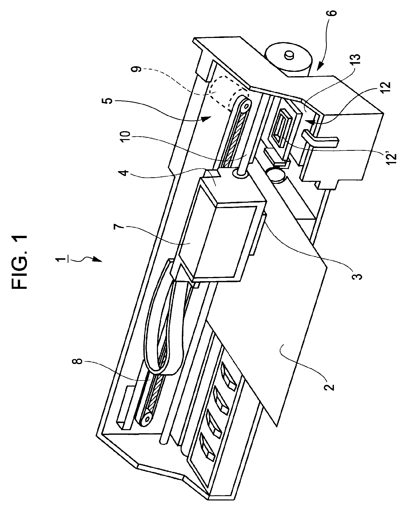
[0032]First, a structure of an ink jet type recording apparatus (a type of a liquid ejecting apparatus, hereinafter referred to as a printer) in which a recording head is mounted will be schematically described with reference to FIG. 1. The exemplified printer 1 is an apparatus for recording an image or the like by ejecting ink in the form of liquid on a surface of a recording medium (object to be ejected) such as a recording p...


PUM


Abstract

There is provided a liquid ejecting head which can introduce a liquid in a liquid storage member to a pressure chamber side via a liquid flow path from a liquid introducing needle and which can eject a liquid in the pressure chamber from a nozzle opening as a liquid drop by operation of a pressure generator. The liquid introducing needle constructed in a hollow needle shape includes an introducing needle portion in which a liquid introducing through hole for introducing a liquid in the liquid storage member is opened, and a cylindrical enlarged diameter straight portion formed at the downstream side of the introducing needle portion and whose inner diameter is enlarged than the inner diameter of the introducing needle portion. The inner space of the enlarged diameter straight portion is to be a bubble chamber which can store a bubble and the enlarged diameter straight portion includes a groove portion extending from the upstream side toward the down stream side on the inner circumference surface.

Description

BACKGROUND[0001]1. Technical Field[0002]The present invention relates to an liquid ejecting head of an ink jet type recording head and the like, and in particular, to an liquid ejecting head for introducing a liquid stored in a liquid storage member to a pressure chamber via a liquid introducing needle and ejecting the liquid introduced into the pressure chamber from a nozzle opening as a liquid drop.[0003]2. Related Art[0004]As for a liquid ejection head for ejecting a liquid from a nozzle opening as a liquid drop by generating pressure fluctuation to a liquid in a pressure chamber, there are included, for example, an ink jet type recording head (hereinafter, simply referred to as a recording head) for used in an image recording apparatus such as an ink jet type recording apparatus (printer), a color material ejecting head for use in color filter manufacture such as a liquid crystal display, an electrode material ejecting head for use in electrode formation such as an organic EL (E...

Claims


Application Information

Patent Timeline
IPC IPC(8): B41J2/135
CPCB41J2/17523B41J2/17513
Inventor OKAZAWA, NORIAKIFUJISHIRO, TAKESHI
Owner SEIKO EPSON CORP
Why Eureka
Try Eureka