Nanostructured Electrode for a Microbattery

a microbattery and nanostructure technology, applied in nanotechnology, non-aqueous electrolyte cells, vapour deposition manufacturing, etc., can solve the problems of limiting the potential use of the battery, affecting the reactivity of lithium metal with regard to the ambient atmosphere, and affecting the reactivity of lithium metal

Inactive Publication Date: 2008-02-21
COMMISSARIAT A LENERGIE ATOMIQUE ET AUX ENERGIES ALTERNATIVES
View PDF13 Cites 105 Cited by
  • Summary
  • Abstract
  • Description
  • Claims
  • Application Information

AI Technical Summary

Benefits of technology

[0011] The object of the invention is to overcome the problems of the state of the art as for the stability of the power storage and supply. More particularly, the invention recommends the use of a new family of electrodes, the architecture and design of which provide suppression of the stresses on the electrolyte during the charging and discharging of the microbattery.

Problems solved by technology

However, the melting point of lithium, 181° C., limits potential use of the battery for high temperatures; in particular, it is impossible to carry out a solder reflow process of the different material layers.
Moreover, the strong reactivity of lithium metal with regard to the ambient atmosphere is a penalty, even for the encapsulation.
Finally, it is impossible to spray lithium metal, so it is necessary to perform thermal evaporation.
Now, insertion of the Li+ ion causes swelling of the material which receives it: even the most performing materials used as insertion anodes, such as Si, lead to significant volume expansions (up to 400%).
The stresses generated by such a difference in volume strongly strain the superimposed layers, and in particular may cause deteriorations, or even cracks, of the juxtaposed electrolyte, which may create short-circuits making the battery inoperative.
The protrusions generated by the deposition however are also the source of strong deformations and of potential breaking of the electrolyte.
Problems of stresses in Li-ion or Li-free microbatteries lead to short-circuit rates of the order of 90% after 1000 charging / discharging cycles (versus 5% for lithium metal anodes).
Such a solution however results in multiplying the number of layers to be deposited (with at least two different targets for the electrolyte), which increases the cost of the manufacturing method, and may only degrade the ionic conductivity of the electrolyte.

Method used


Image

  • Nanostructured Electrode for a Microbattery
  • Nanostructured Electrode for a Microbattery

Examples


Embodiment Construction

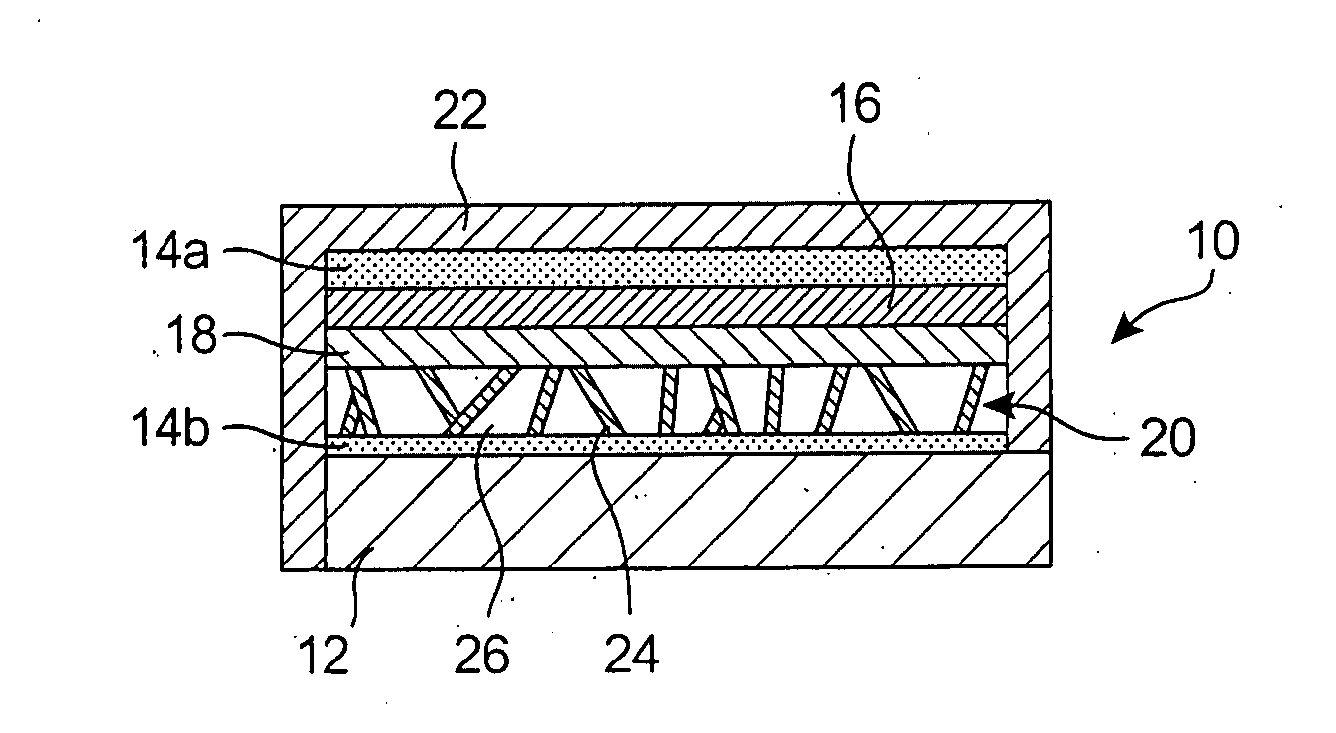
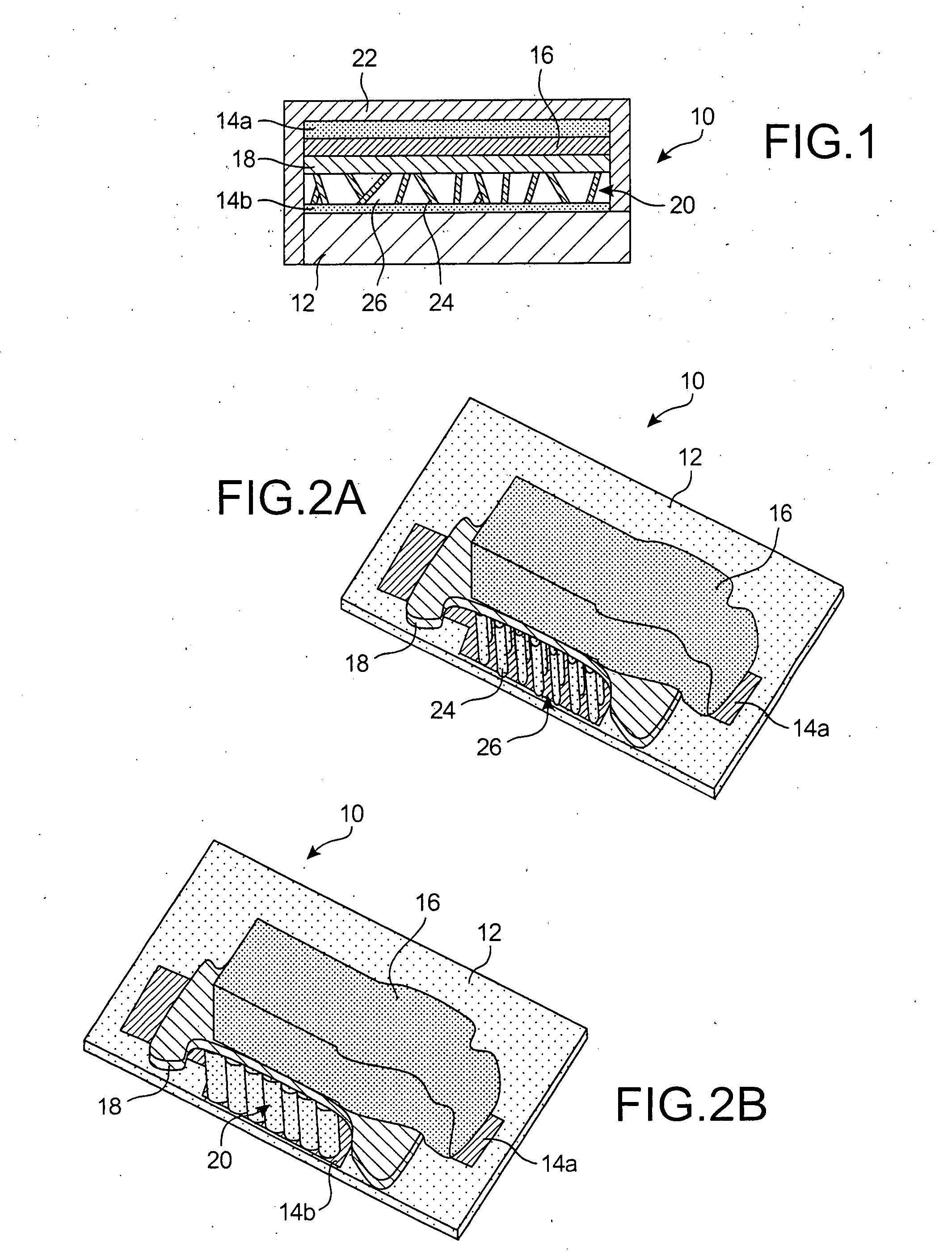
[0020] As schematized in FIG. 1, a power storage device usually comprises a substrate 12, cathode 14a and anode 14b collectors (the latter may be integral with the substrate 12), a cathode 16, an electrolyte 18, and an anode 20. Moreover, the microbattery 10 may be protected by an encapsulation layer 22: the electrodes 16, 20, notably when they are in lithium, are indeed very reactive towards air, and it may be advantageous to also encapsulate the other components 14, 18.

[0021] The total thickness of the stack 14, 16, 18, 20 is usually between 10 and 50 μm, advantageously of the order of 15 μm. Such a microbattery 10, except for the anode 20 which will be described later on, may be made by any known technique, and in particular with different materials:

[0022] The current collectors 14 are metal and may for example be deposits based on Pt, Cr, Au, Ti.

[0023] The positive electrode 16 may notably consist of LiCoO2, LiNiO2, LiMn2O4, CuS, CuS2, WOySz, TiOySz, V2O5, deposited by a stan...


PUM

PropertyMeasurementUnit
diameteraaaaaaaaaa
diameteraaaaaaaaaa
diameteraaaaaaaaaa

Abstract

A new anode configuration (20) is proposed for a lithium microbattery (10). The anode (20) preferably consists of nanotubes or of nanowires (24) such that the empty space (26) left between the different components (24) provides compensation for the inherent swelling upon discharging the microbattery (10). With the absence of stresses on the electrolyte (18), the lifetime of the battery (10) may be increased.

Description

TECHNICAL FIELD [0001] The invention relates to the field of power storage devices, and mainly of microbatteries made in thin films by vacuum deposition methods. [0002] More particularly, the invention relates to an electrode for a battery, notably a lithium battery, the structure of which is defined so as to optimize reliability of power storage. STATE OF THE PRIOR ART [0003] Among power storage devices, microbatteries which are particularly used, so-called <<fully solid>>batteries, are in the form of films: all the components of the microbattery, i.e., the current collectors, the positive and negative electrodes, the electrolyte and even the encapsulation, are thin layers, obtained by deposition, mainly by physical vapor deposition (PVD) or chemical vapor deposition (CVD). The techniques used allow objects to be made with any shapes. [0004] As usual, the operating principle of such a battery is based on the insertion and removal, also called <<disinsertion>>...

Claims


Application Information

Patent Timeline
Patent Type & Authority Applications(United States)
IPC IPC(8): H01M10/36H01M4/04H01M4/58H01M4/133H01M4/134H01M4/1393H01M4/1395H01M4/587H01M10/0525H01M10/0562H01M10/0585
CPCB82Y30/00Y02E60/122H01M4/0428H01M4/133H01M4/134H01M4/1393H01M4/1395H01M4/587H01M6/40H01M10/0525H01M10/0562H01M10/0585H01M2300/0068H01M2300/0094H01M4/0423Y02E60/10Y02P70/50
Inventor SALOT, RAPHAELGAILLARD, FREDERICROUVIERE, EMMANUELLEMARTIN, STEVE
Owner COMMISSARIAT A LENERGIE ATOMIQUE ET AUX ENERGIES ALTERNATIVES
Why Eureka
Try Eureka