Radio Relay Communication Method, Radio Base Station, and Radio Relay Station in Radio Communication System

Inactive Publication Date: 2008-02-21
FUJITSU LTD
View PDF18 Cites 59 Cited by
  • Summary
  • Abstract
  • Description
  • Claims
  • Application Information

AI Technical Summary

Benefits of technology

[0043](1) By controlling (adjusting) a transmit timing of a radio base station or a receiving timing of a mobile station (or, a receiving timing of a radio base station or a transmit timing of a mobile station) according to the receiving (or transmit) timing in the mobile station determined based on the time lag information in a radio relay station, a receiving timing shift in the radio base station or mobile station accompanying a relay delay caused by passing through the radio relay station can be absorbed to improve a ratio of successful recept

Problems solved by technology

However, such radio relay communication has problems described below.
This causes problems described below.
Thus, a transmit timing or receiving timing of messages and data managed separately by the BS 100 and MS 300 is shifted and messages and data do not arrive at the BS 100 or MS 300 in planned receiving timings, leading to a reception failure.
In such cases, the planned receiving timing at the MS 300 assumed by the BS 100 and the planned receiving timing calc

Method used


Image

  • Radio Relay Communication Method, Radio Base Station, and Radio Relay Station in Radio Communication System
  • Radio Relay Communication Method, Radio Base Station, and Radio Relay Station in Radio Communication System
  • Radio Relay Communication Method, Radio Base Station, and Radio Relay Station in Radio Communication System

Examples


Embodiment Construction

[0078]An embodiment of the present invention will be described below in detail with reference to drawings. It is needless to say that the present invention is not limited to the embodiment and can be carried out in various modifications without departing from the spirit of the present invention.

[0079][A] Description of an Embodiment

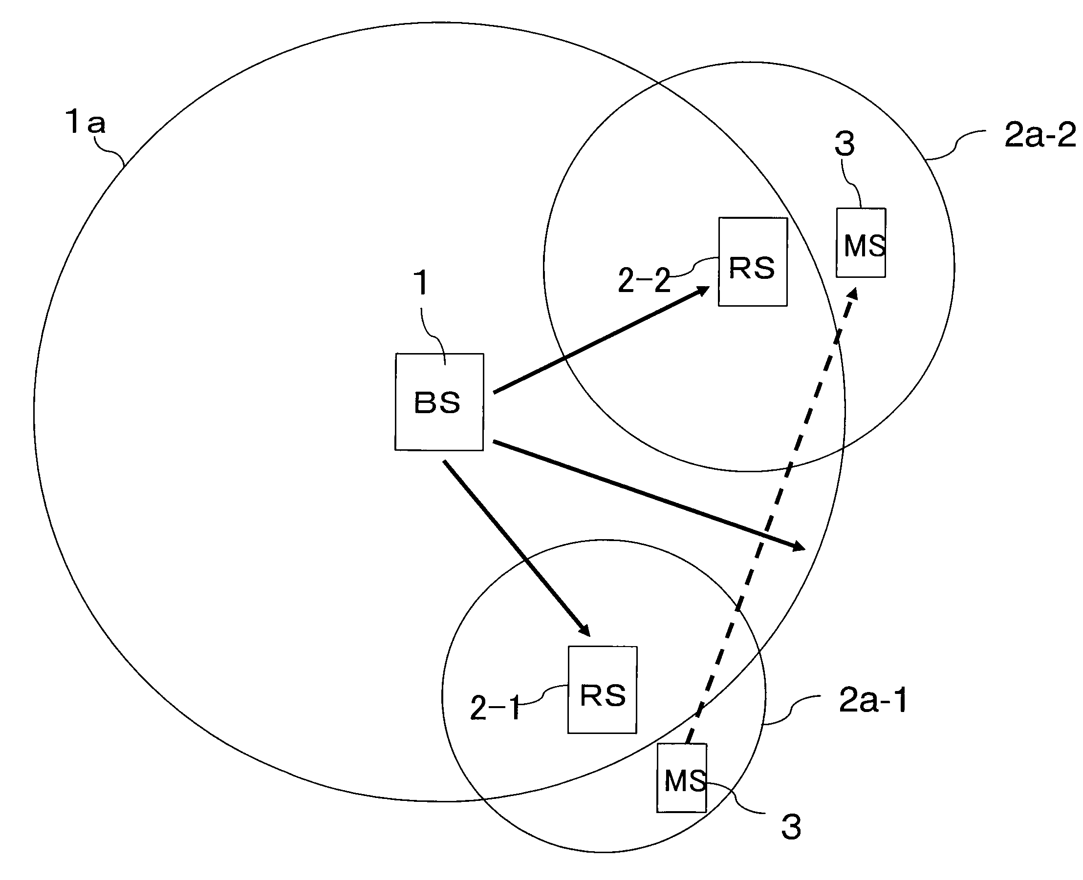
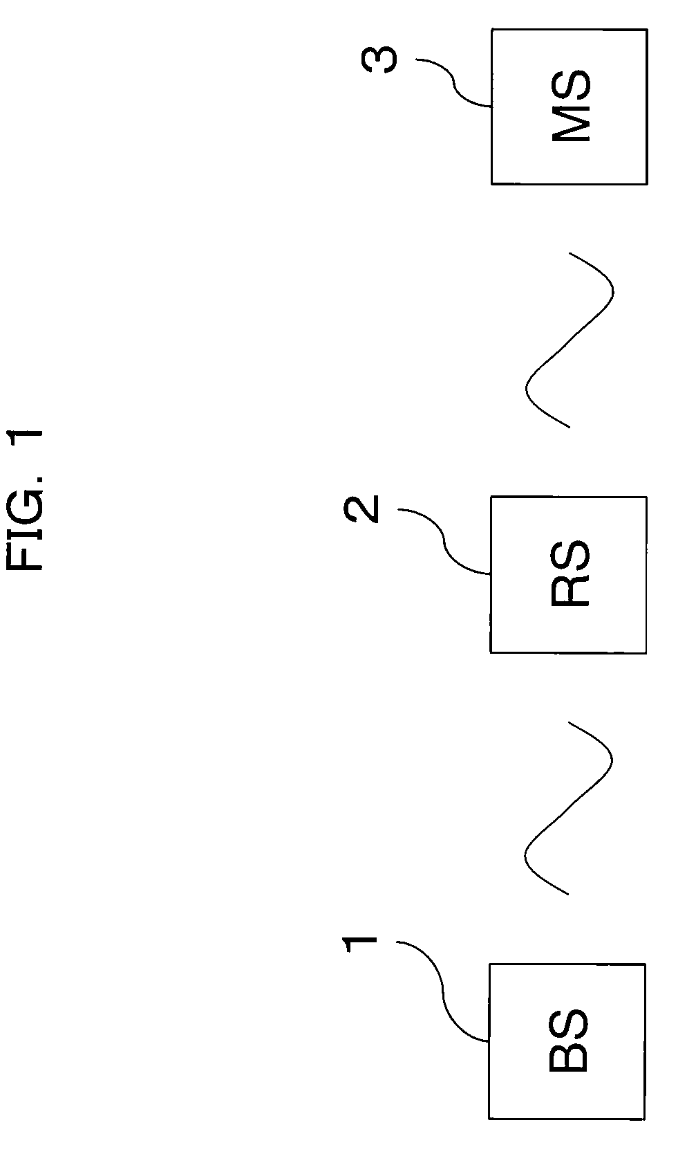
[0080]FIG. 1 is a block diagram showing the configuration of a radio communication system according to an embodiment of the present invention, and the radio communication system shown in FIG. 1 is comprised of a radio base station (BS) 1, a mobile station (MS) 3 as a wireless terminal equipped with a radio communication function such as a mobile phone and laptop PC, and a radio relay station (RS) 2 disposed between the BS 1 and MS 3. In the present embodiment, the RS 2 corresponds to a mobile station in relation to the BS 1 and operates as a radio base station in relation to the MS 3, and temporarily receives a radio (RF) signal transmitted by the BS 1 or...


PUM


Abstract

Correct reception of messages and data by a mobile station or radio base station is enabled in a planned timing by adjusting a receiving or transmit timing in consideration of a time (an occurrence of a time lag) required for relay processing in a radio relay station within a radio communication system.
For that purpose, time lag information related to a relay delay due to relay processing in the radio relay station is set to the radio base, the receiving timing of the mobile station is determined based on the time lag information, and the transmit timing of the radio base station 1 or the receiving timing of the mobile station is controlled according to the determined receiving timing.

Description

CROSS REFERENCE TO RELATED APPLICATION(S)[0001]This application is based on and hereby claims priority to two Japanese Applications No. 2006-222703 filed on Aug. 17, 2006 and No. 2006-290000 filed on Oct. 25, 2006 in Japan, the contents of which are hereby incorporated by reference.BACKGROUND OF THE INVENTION[0002](1) Field of the Invention[0003]The present invention relates to a radio relay communication method, a radio base station, and a radio relay station in a radio communication system.[0004](2) Description of Related Art[0005]In recent years, a technology called WiMAX (Worldwide Interoperability for Microwave Access) has attracted attention as one of radio communications technologies. WiMAX is a technology developed as a technique to construct Wireless MAN by making a communication operator and user homes connectable by radio instead of telephone lines or optical fiber lines and making a MAN (Metropolitan Area Network) wireless, which is a wide area network mutually connectin...

Claims


Application Information

Patent Timeline
IPC IPC(8): H04B7/15
CPCH04B7/155H04W56/00H04B7/2606B66B9/003E04F11/002E04G27/00F16C11/04
Inventor NAKATSUGAWA, KEIICHI
Owner FUJITSU LTD
Why Eureka
Try Eureka