Apparatus and method for performing spinal surgery

a spinal surgery and apparatus technology, applied in the field of spinal surgery, can solve the problems of loss of disc height and alteration of annulus fibrosis, loss of motion at the fused vertebral joint, and significant pain for individuals with damaged or degenerated discs

Inactive Publication Date: 2008-02-21
DYNAMIC SPINE
View PDF6 Cites 74 Cited by
  • Summary
  • Abstract
  • Description
  • Claims
  • Application Information

AI Technical Summary

Problems solved by technology

Individuals with damaged or degenerated discs often experience significant pain.
The pain results, in part, from instability in the intervertebral joint due to a loss of hydrostatic pressure in the nucleus pulposus, which leads to a loss of disc height and altered loading of the annulus fibrosis.
Although spinal fusion may alleviate pain associated with degenerative disk disease, it also results in loss of motion at the fused vertebral joint.
Lack of motion at the fused site puts abnormal loads on the adjacent discs above and below the fusion.
This additional pressure may cause the adjacent discs to degenerate and produce pain, thereby recreating the problem which originally existed.
Existing prosthetic devices have met with limited success in reproducing the biomechanics of a natural disc.
Although the hinged disc allows forward bending between adjacent vertebrae, the hinged disc does not allow axial compression or lateral flexion.
Nor does it allow axial rotation of the vertebral column at the site of the implant.
Therefore, the Hedman et al. device lacks many of the biomechanics of a natural disc.
Likewise, the prosthetic disc device disclosed in U.S. Pat. No. 4,309,777 to Patil does not replicate natural motion between adjacent discs.
Thus, the Patil device does not enable natural flexion of the spine in any direction.
In addition, the highly constrained motion of the Patil device can lead to high device / tissue interface stresses and implant loosening.
Other synthetic devices use plastic or elastomeric components which, over a lifetime, produce debris from wear and possible unknown side effects.

Method used


Image

  • Apparatus and method for performing spinal surgery
  • Apparatus and method for performing spinal surgery
  • Apparatus and method for performing spinal surgery

Examples


Embodiment Construction

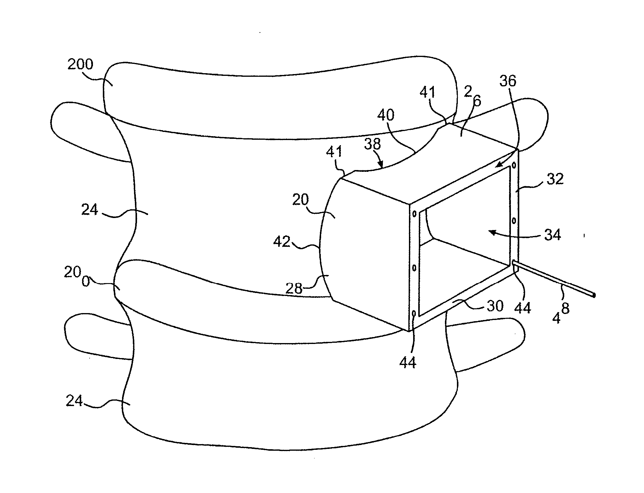
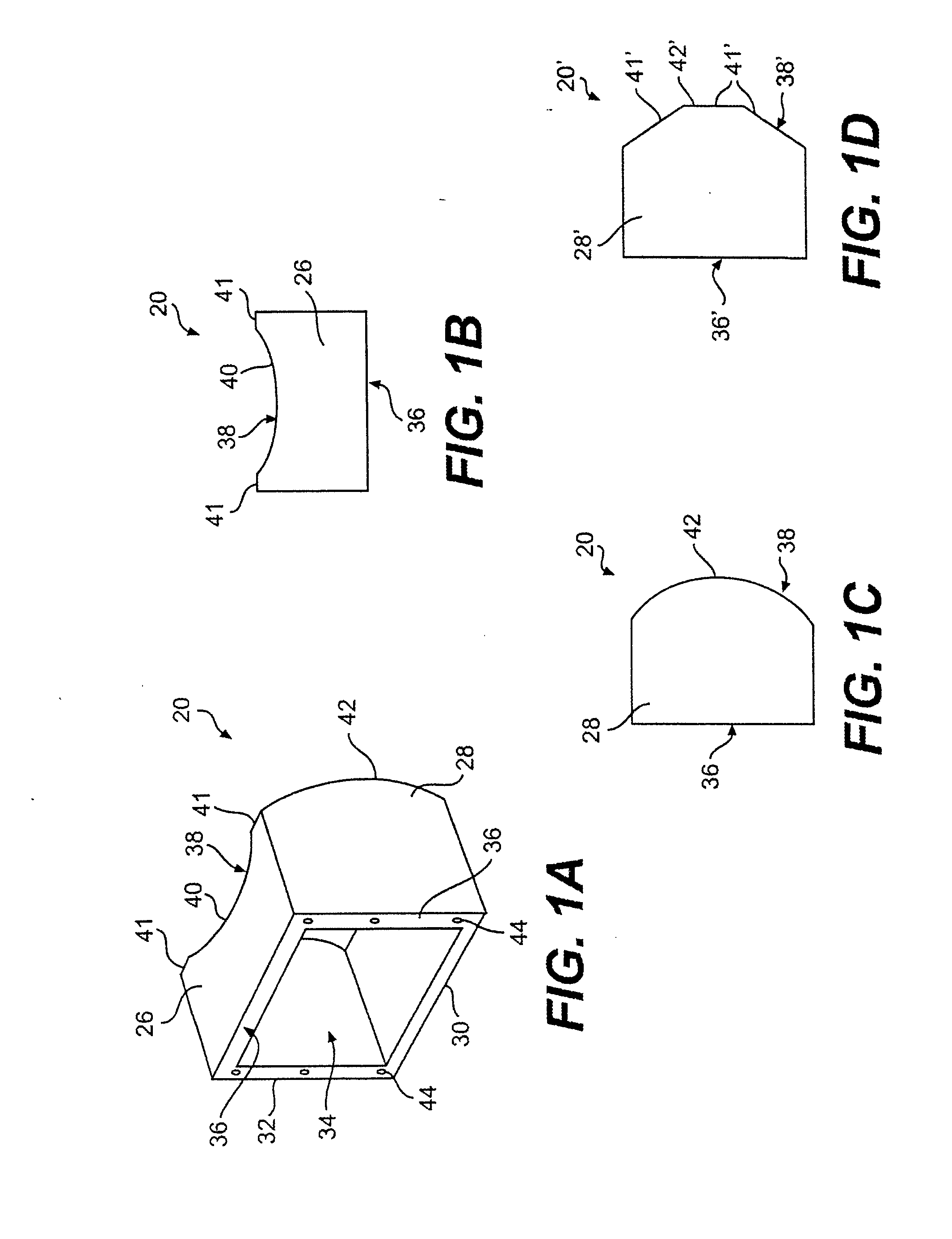
[0067] Referring now to the drawings, wherein like numerals indicate like parts, and initially to FIGS. 1A-1C and 8, there will be seen a cutting guide 20 for use in removing bone 22 from a vertebral body 24. The cutting guide is designed to be placed into contact with the outer surface of the vertebral body 24 to “guide” a surgical instrument as it cuts through the cortical bone of the vertebral body, as shown in FIGS. 8 and 9A-9B and as later described in more detail. In this regard, the cutting guide 20 has a sidewall that defines an internal cavity 34 extending through the cutting guide 20. The sidewall generally has four walls 26, 28, 30, 32 arranged to form a rectangular cross-section. Although the cavity 34 is preferably rectangular in cross section, the walls 26, 28, 30, 32 can be configured to define a cavity that is square in cross-section or any other suitable geometric shape.

[0068] The cutting guide 20 has a first edge 38 to face toward and to contact the vertebral body...


PUM


Abstract

A cutting guide for use in spinal surgery includes a sidewall defining an internal cavity. A chisel guide, for use with the cutting guide, includes a first block member to be inserted into the internal cavity of the cutting guide to position the first block member adjacent the vertebral body. The chisel guide also includes a second block member connected to the first block member. An apparatus for creating a cavity in a-vertebral body endplate and in an intervertebral disc may be a compressor or a distractor having at least one cutting implement thereon. A tensioner determines a proper elongation distance in a prosthesis implanted in a vertebral body.

Description

BACKGROUND OF THE INVENTION [0001] This invention relates to the field of spinal surgery. More specifically, this invention relates to apparatuses for creating cavities in vertebral bodies and in intervertebral discs located between the vertebral bodies. This invention also relates to methods for creating such cavities. Once the cavities are created with the apparatuses and according to the methods of the present invention, an intervertebral prosthetic device, designed to replace a damaged intervertebral disc, can be implanted in the cavities. Moreover, the implanted device may be used in vertebral body fusion or in reconstruction of mobile discs through spinal arthroplasty (i.e., disc replacement). [0002] The human spine is a flexible structure comprised of twenty-five vertebrae. Intervertebral discs separate and cushion adjacent vertebrae. The intervertebral discs act as shock absorbers and allow bending between the vertebrae. [0003] An intervertebral disc comprises two major comp...

Claims


Application Information

Patent Timeline
Patent Type & Authority Applications(United States)
IPC IPC(8): A61F5/00A61B17/00A61B17/02A61B17/15A61B17/16A61B17/17A61B17/32A61B19/00
CPCA61B17/025A61B17/15A61B17/1604A61B17/1611A61B17/1617A61B2019/304A61B17/1735A61B17/1757A61B2017/00004A61B2017/0256A61B2017/320052A61B17/1671A61B2090/034
Inventor BUTTERMANN, GLENN ROBINCOOPER, DOUG WAYNE
Owner DYNAMIC SPINE
Why Eureka
Try Eureka