Maximum torque driving of robotic surgical tools in robotic surgical systems

a robotic surgical and maximum torque technology, applied in the direction of surgical forceps, program control, instruments, etc., can solve problems such as slack in wires or cables, and particularly problemati

Active Publication Date: 2008-02-21
INTUITIVE SURGICAL OPERATIONS INC
View PDF25 Cites 863 Cited by
  • Summary
  • Abstract
  • Description
  • Claims
  • Application Information

AI Technical Summary

Benefits of technology

[0031]FIG. 16A schematically illustrates a high level control architecture model of a master / slave surgical robotic system.
[0032]FIG. 16B shows a block diagram representing control steps followed by the control system of the minimally invasive surgical apparatus in effecting control between master positional and orientational movement and slave end effector positional and orientational movement.

Problems solved by technology

However as the robotic surgical gripping instrument or tool and its cables are used over and over again after being re-sterilized, it ages and the wires or cables that open and close jaws of the tool may stretch or the instrument may compress causing slack in the wires or cables.
With stretched cables or a compressed instrument limiting the position of the input disk to the predetermined position limit may not allow a maximum torque to be reached.
This may be particularly problematic during robotic surgical procedures.

Method used


Image

  • Maximum torque driving of robotic surgical tools in robotic surgical systems
  • Maximum torque driving of robotic surgical tools in robotic surgical systems
  • Maximum torque driving of robotic surgical tools in robotic surgical systems

Examples


Embodiment Construction

[0043]In the following detailed description of the embodiments of the invention, numerous specific details are set forth in order to provide a thorough understanding of the embodiments of the invention. However, it will be obvious to one skilled in the art that the embodiments of the invention may be practiced without these specific details. In other instances well known methods, procedures, components, and circuits have not been described in detail so as not to unnecessarily obscure aspects of the embodiments of the invention.

Introduction

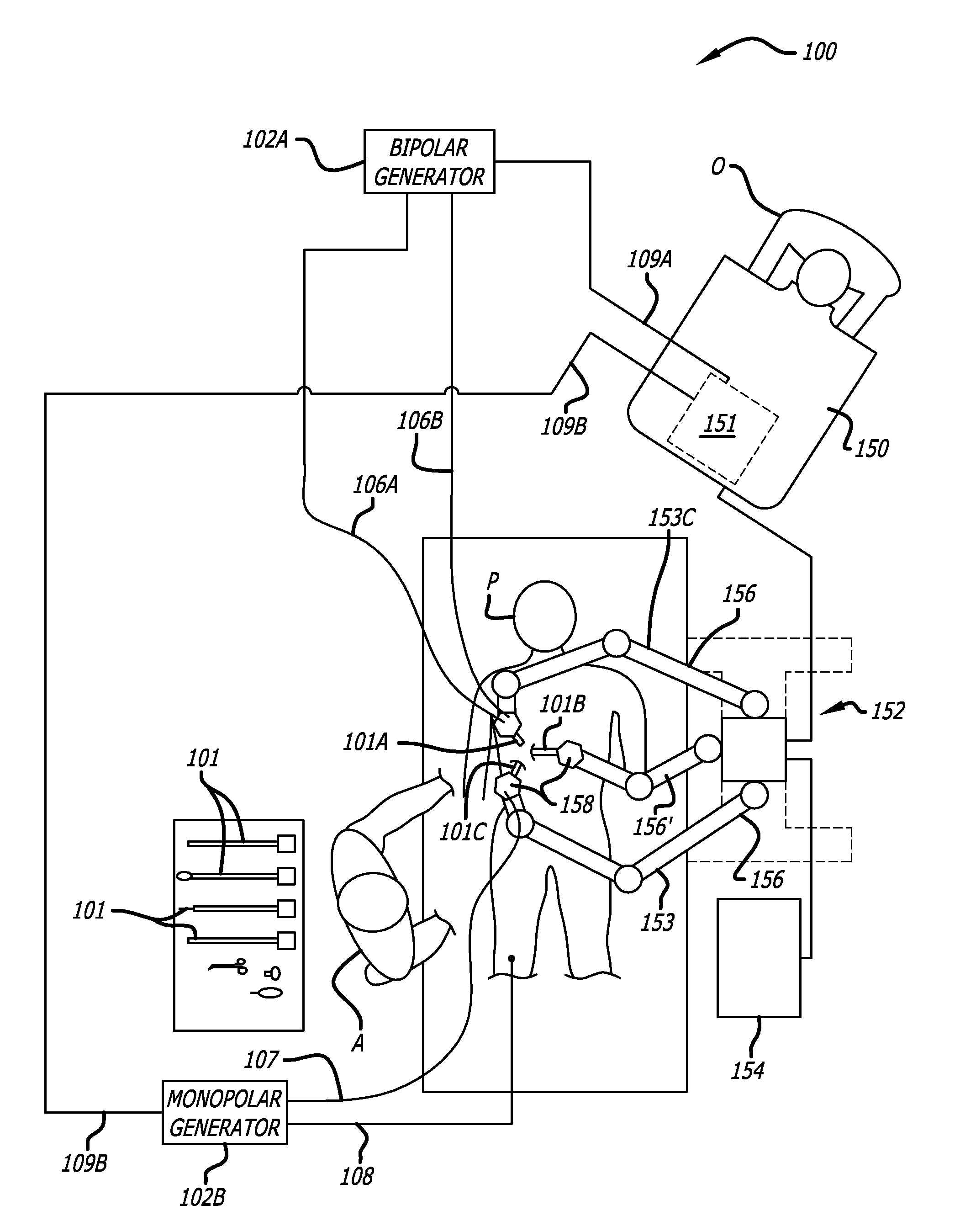
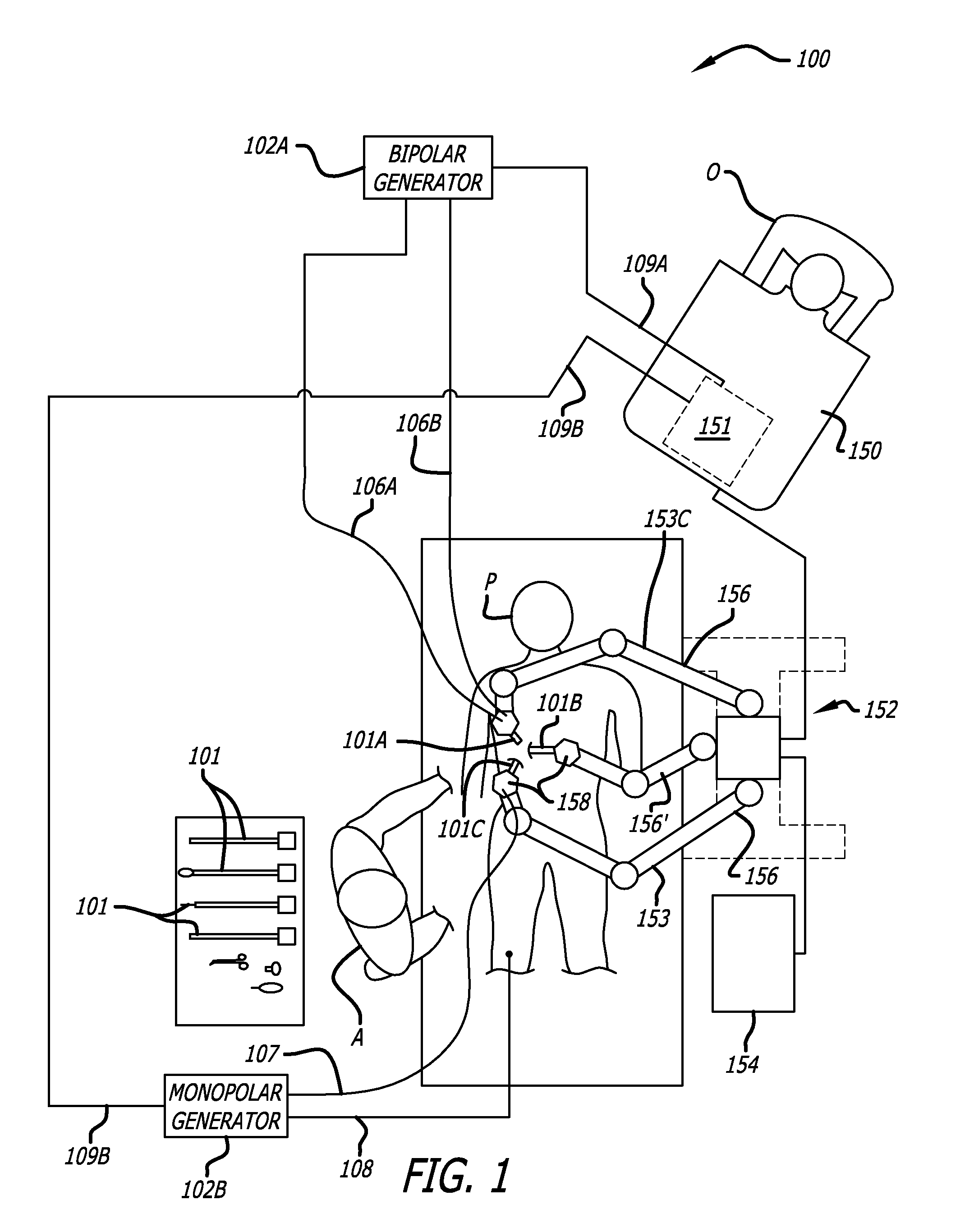
[0044]The embodiments of the invention include methods, apparatus, and systems to drive robotic gripping and electro-surgical tools to maximum joint torque throughout their life. A servomotor or driver is limited by a maximum torque setting so that the end effectors of a robotic surgical tool can be driven to the maximum allowed torque. This ensures that input disks at the interface of the tool continue to rotate until the maximum torque setting h...


PUM


Abstract

In one embodiment of the invention, a control system for a robotic surgical instrument is provided including a torque saturation limiter, a torque to current converter coupled to the torque saturation limiter, and a motor coupled to the torque to current converter. The torque saturation limiter receives a desired torque signal for one or more end effectors and limits the desired torque to a range between an upper torque limit and a lower torque limit generating a bounded torque signal. The torque to current converter transforms a torque signal into a current signal. The motor drives an end effector of one or more end effectors to the bounded torque signal in response to the first current signal.

Description

CROSS-REFERENCE TO RELATED APPLICATIONS[0001]This non-provisional United States (U.S.) patent application claims the benefit of U.S. Provisional Patent Application No. 60 / 817,931 filed on Jun. 29, 2006 by inventors Scott Manzo, et al., entitled Maximum Torque Driving for Robotic Surgical Tools.[0002]This non-provisional U.S. patent application further is related to and incorporates by reference the full disclosure of U.S. Pat. No. 6,424,885 filed by Niemeyer et al. on Aug. 13, 1999, entitled “Camera Referenced Control in a Minimally Invasive Surgical Apparatus”; U.S. Pat. No. 6,594,552, filed by Nowlin et al. on Apr. 6, 2000, entitled “Grip Strength with Tactile Feedback for Robotic Surgery”; U.S. Pat. No. 6,840,938, filed by Morely et al. on Dec. 21, 2001, entitled “Bipolar Cauterizing Instrument”; U.S. Pat. No. 6,659,939, filed by Moll et al. on Nov. 3, 1999, entitled “Cooperative Minimally Invasive Telesurgical System”; and U.S. Pat. No. 6,493,608, filed by Gunter D. Niemeyer on ...

Claims


Application Information

Patent Timeline
Patent Type & Authority Applications(United States)
IPC IPC(8): G06F19/00
CPCA61B1/00149A61B2017/00477A61B19/5212A61B2017/00203A61B2017/00482A61B2017/2825A61B2017/2929A61B2017/2932A61B2019/2223A61B2019/2234A61B2019/2242A61B2019/2246A61B2019/2269A61B2019/2292A61B2019/301A61B2019/448A61B2019/464B25J9/1689G05B2219/40144G05B2219/42289G05B2219/45123G06F19/3406G06F19/3418G06F19/3481A61B19/2203A61B34/30A61B34/37A61B34/71A61B34/74A61B34/76A61B90/361A61B90/98A61B2034/305A61B2034/715A61B2090/031A61B2090/064G16H20/40G16H40/63Y10S901/02Y10S901/19Y10S901/21A61B2017/2829
Inventor MANZO, SCOTTSWARUP, NITISH
Owner INTUITIVE SURGICAL OPERATIONS INC
Why Eureka
Try Eureka