Rotary table with frameless motor

a frameless motor and rotary table technology, applied in the field of rotary tables, can solve the problems of inability to correct for such inaccuracies, encoders are unable to recognize position errors, and affect the accuracy of such conventional indexers, so as to avoid backlash-related inaccuracies and limit disadvantageous thermal expansion of the table

Inactive Publication Date: 2008-02-28
HARDINGE INC
View PDF32 Cites 42 Cited by
  • Summary
  • Abstract
  • Description
  • Claims
  • Application Information

AI Technical Summary

Benefits of technology

[0006]An aspect of one or more embodiments of the present invention provides a rotary table that utilizes direct drive motor(s) to precisely angularly position a work piece for milling operations in a milling machine.
[0007]Another aspect of one or more embodiments of the present invention provides a rotary table that utilizes direct drive motor(s) with angle encoders mounted directly to the output shaft. Such a direct drive configuration avoids the backlash-related inaccuracies associated with worm drive indexers.
[0008]According to a further aspect of one or more of these embodiments, the motor(s) are thermally insulated from the remainder of the rotary table so as to limit heat transfer from the motor and / or associated bearings to the remainder of the table, thereby limiting disadvantageous thermal expansion of the table.
[0009]According to a further aspect of one or more of these embodiments, the motor(s) are mounted to the rotary table via a motor support that is symmetrical with respect to an axis of the motor. Such symmetrical mounting allows the motor and surrounding components to thermally expand and contract symmetrically with respect to the motor's axis so as not to disadvantageously misalign the axis relative to the remainder of the rotary table.

Problems solved by technology

Unfortunately, gear backlash between the worm gear and driven gear impairs the accuracy of such conventional indexers 2040.
When the encoder is mounted to the motor, the encoder is unable to recognize position errors stemming from gear backlash or correct for such inaccuracies.
The inaccuracies associated with backlash increase as the gears wear over time.
Moreover, the space occupied by such gear transmissions reduces the space available for a work piece 2020 within the confined working space of the milling machine 2010.

Method used


Image

  • Rotary table with frameless motor
  • Rotary table with frameless motor
  • Rotary table with frameless motor

Examples


Embodiment Construction

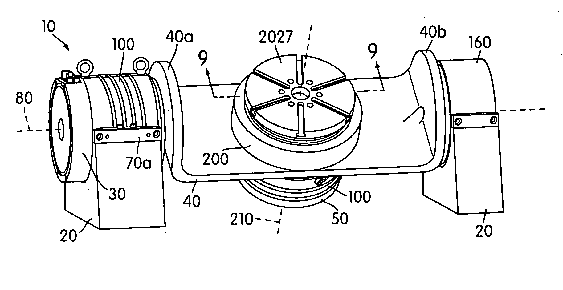
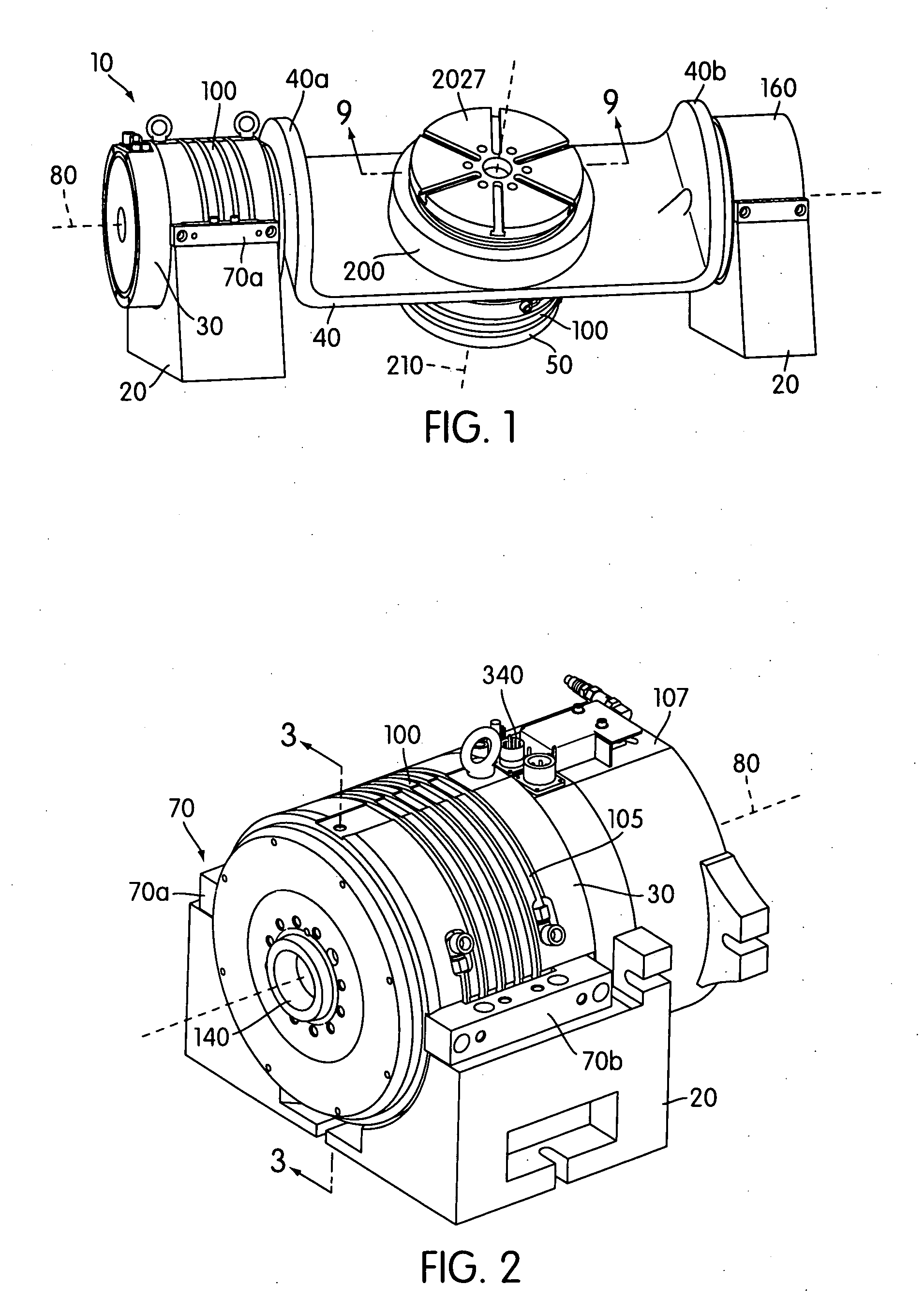
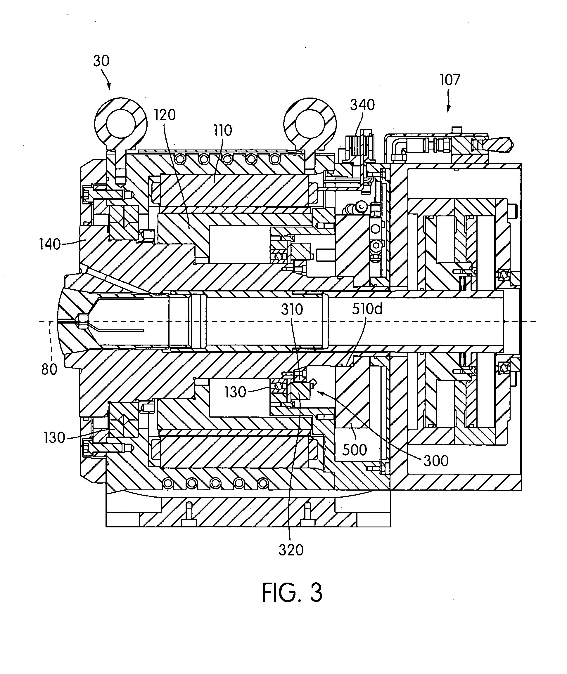
[0038]FIGS. 1-5, 7, and 9 illustrate a two-axis rotary table 10 according to an embodiment of the present invention. The rotary table 10 comprises a base 20, a horizontal direct drive motor 30, a trunnion 40, and a vertical direct drive motor 50.

[0039]As shown in FIG. 7, the base 20 is constructed and arranged to operatively connect to the platform 2025 of the milling machine 2010. Accordingly, the milling machine 2010 illustrated in FIG. 6 may be upgraded by replacing the conventional rotary table 2000 with the rotary table 10. Suitable fasteners (e.g., bolts, screws, clamps, welds, etc.) may be used to rigidly connect the rotary table 10 to the platform 2025 of the milling machine 2010. Alternatively, the base 20 may operatively connect to the milling machine via integral formation with the milling machine or a component thereof (e.g., the platform 2025).

[0040]While the illustrated rotary table 10 is used in connection with a vertical milling machine, the rotary table 10 may alter...


PUM

PropertyMeasurementUnit
angleaaaaaaaaaa
thermal conductivityaaaaaaaaaa
axial thermal expansionaaaaaaaaaa

Abstract

A rotary table for a material processing machine such as a vertical milling machine utilizes direct drive motor(s) to precisely angularly position a work piece along one or more pivotal axes. The direct drive motor(s) are thermally insulated from the remainder of the machine to limit misaligning thermal expansion of the components of the machine. The motors may be symmetrically attached to their respective supports such that thermal expansion / contraction of the motor and surrounding components occurs symmetrically with respect to the motor to limit misalignment of the motor's rotational axis. A motor may mount to its respective support only at a first axial end thereof such that thermal expansion of a second axial end of the motor does not adversely shift the position of the first end. Axially narrow clamps selectively secure the rotors of the motors in desired positions.

Description

BACKGROUND OF THE INVENTION[0001]1. Field of the Invention[0002]The present invention relates generally to rotary tables for multi-axis milling machines, and relates specifically to motors used to angularly position work pieces in such milling machines[0003]2. Description of Related Art[0004]As shown in FIG. 6, rotary tables 2000 are used in connection with milling machines 2010 to precisely angularly position work pieces 2020 for milling operations. The rotary table 2000 mounts to a platform 2025 of the milling machine 2010. A workholding device 2027 (e.g., jaw chuck, collet system, clamp, etc.) connects to the rotary table 2000 to mount the work piece 2020 to the rotary table. Such rotary tables 2000 control the rotational orientation of the work piece 2020 in one or more axes. The milling machine 2010 moves a toolspindle 2030 relative to the work piece 2020 in three orthogonal translational directions (i.e., along orthogonal X, Y, and Z axes). In a 4 axis milling machine, the rot...

Claims


Application Information

Patent Timeline
Patent Type & Authority Applications(United States)
IPC IPC(8): B23C1/14
CPCB23Q1/01B23Q1/52B23Q11/0003Y10T409/305824B23Q2210/004Y10T29/5114B23Q2220/004B23Q11/127
Inventor SOROKA, DANIEL P.KESTERKE, RICHARDCOLVIN, JOSEPH T.WEIDMAN, LLOYDTURNER, JEREMY
Owner HARDINGE INC
Why Eureka
Try Eureka