Motor actuator

a motor actuator and actuator technology, applied in the direction of lighting and heating apparatus, heating types, domestic cooling apparatus, etc., can solve the problems of system not being able to be modified to the signal control system, and the reliability of the “on” or “off” signal is not satisfactory

Active Publication Date: 2008-02-28
SANKYO SEIKI MFG CO LTD
View PDF1 Cites 9 Cited by
  • Summary
  • Abstract
  • Description
  • Claims
  • Application Information

AI Technical Summary

Benefits of technology

[0006] In view of the problems described above, an embodiment of the present invention may advantageously provide a

Problems solved by technology

In the conventional micro switch system as described above, there are variations of a pushing quantity, force, and/or time interval of a button of the micro switch and variations of an “ON” position and an “OFF” position and, in addition, there is further a variation in assembling accuracy and thus reliabili

Method used


Image

  • Motor actuator
  • Motor actuator
  • Motor actuator

Examples


Embodiment Construction

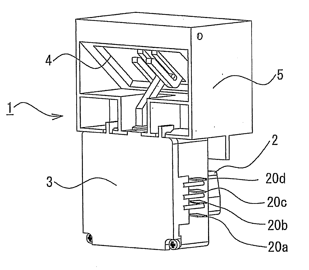
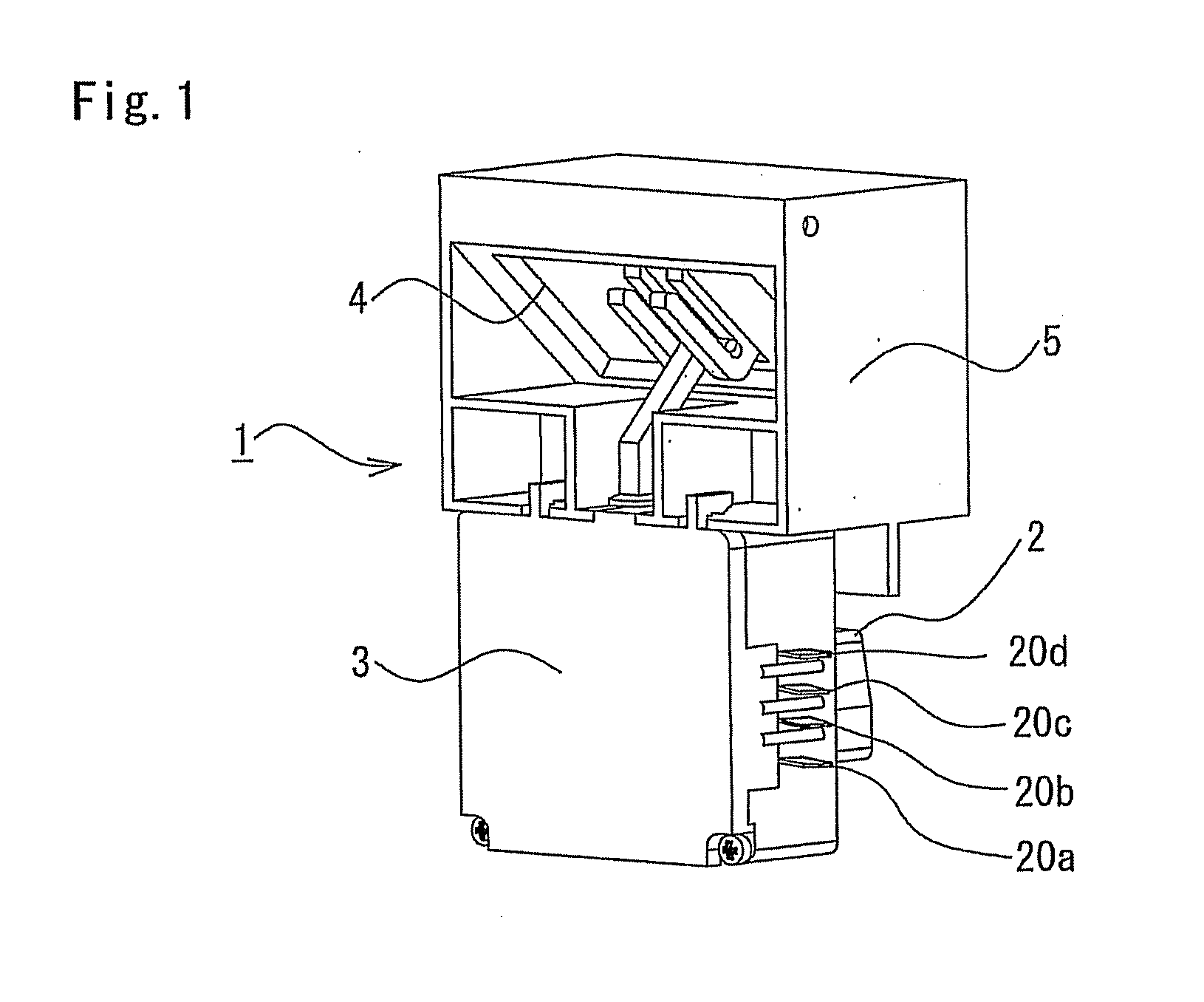
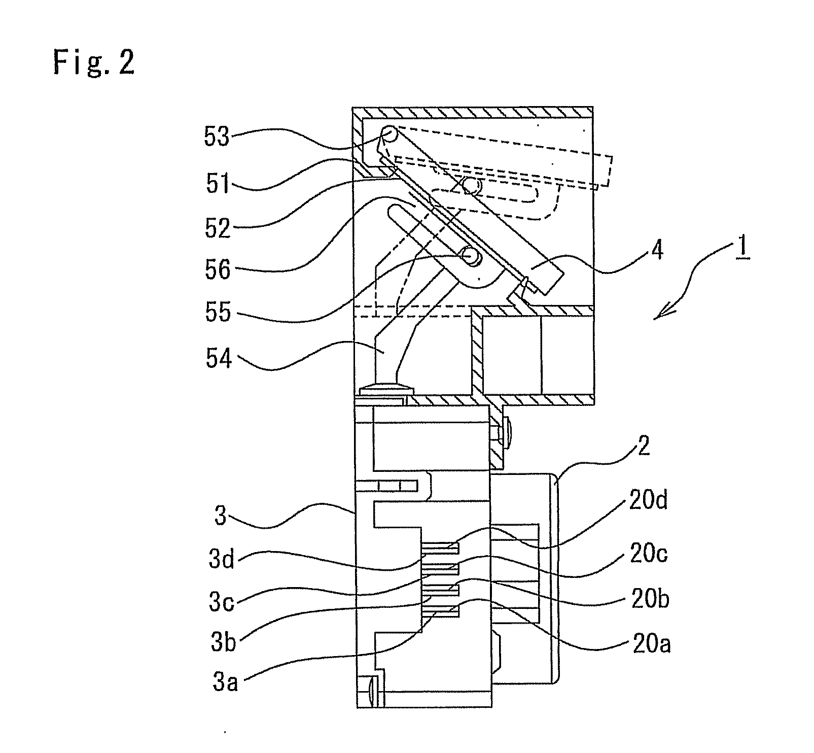
[0028] An embodiment of the present invention will be described in detail below with reference to the accompanying drawings. FIG. 1 is a perspective appearance view showing a motor type damper device, which is used as an opening / closing device disposed in a passage for cold air of a refrigerator, and which is an example of a motor actuator in accordance with an embodiment of the present invention. FIG. 2 is a side view showing a cross section of a damper part and a side face of a housing case of the motor type damper device in FIG. 1, which is viewed from its side face side. FIG. 3 is a front view showing an internal structure of a housing case of the motor type damper device shown in FIG. 1.

[0029] The motor type damper device 1 shown in FIG. 1 includes a motor 2 as a drive device, a housing case 3 in which a driving force transmission means is accommodated, and a driven member which is adjacently provided on an upper side of the box-shaped housing case 3. The driving force transmi...


PUM


Abstract

A motor actuator may include a motor, a cam driven by the motor, switch contact pieces operated by the cam, a housing case which accommodates at least the cam, the switch contact pieces, and connection terminals attached to the housing case for connecting an external power supply to the motor. The cam is formed with a step part for operating the switch contact pieces and the switch contact pieces are structured as a position sensor. The connection terminals may include a first switch terminal, a second switch terminal, a first motor terminal, and a second motor terminal. The housing case is formed with at least three cut-out portions so that the first switch terminal, the first motor terminal and the second switch terminal are disposed in this order.

Description

CROSS REFERENCE TO RELATED APPLICATION [0001] The present invention claims priority under 35 U.S.C. § 119 to Japanese Application No. 2006-224927 filed Aug. 22, 2006, which is incorporated herein by reference. FIELD OF THE INVENTION [0002] An embodiment of the present invention may relate to a motor actuator. More specifically, an embodiment of the present invention may relate to a motor actuator which is preferably used in a motor type damper device or the like for controlling, for example, cold air in a refrigerator. BACKGROUND OF THE INVENTION [0003] For example, a motor type damper device which is an example of a motor actuator is used in a refrigerator. In a refrigerator, cold air which is cooled by a compressor is supplied into a chamber and, when a temperature in the chamber becomes a predetermined value or lower, supply of the cold air is stopped. When the temperature rises, cold air is supplied to the chamber to maintain the temperature in the chamber in a prescribed state....

Claims


Application Information

Patent Timeline
IPC IPC(8): H02K7/00H02K11/00H02K5/22
CPCF24F2013/1433F25D17/045H02K11/0015H02K7/075H02K5/225H02K11/21
Inventor ITO, HIDEAKIAKABANE, TOKUYUKI
Owner SANKYO SEIKI MFG CO LTD
Why Eureka
Try Eureka