Automatic External Switch Detection In Synchronous Switching Regulator Controller

Active Publication Date: 2008-02-28
MICREL
View PDF2 Cites 29 Cited by
  • Summary
  • Abstract
  • Description
  • Claims
  • Application Information

AI Technical Summary

Benefits of technology

[0010]According to one embodiment of the present invention, a synchronous switching regulator controller includes a first switch driver coupled to a first terminal to provide a first driving signal, a second switch driver coupled to a second terminal to provide a second driving signal, a PWM ramp clock generator providing a PWM ramp clock signal to a PWM comparator and a control logic circuit generating control signals for the first and second switch drivers based at least in part on the output signal of the PWM comparator. The synchronous switching regulator controller includes a switch detection circuit receiving a power cycle signal indicating that the synchronous switching regulator controller is to be turned on and the PWM ramp

Problems solved by technology

However, as synchronous controllers are being operated at higher and higher frequencies, the switching of the open node may cause undesired problems.
When an open node is driven in high frequency, the open node becomes an RF transmission line, causing unwanted electromagnetic interference (EMI) noise.
Furthermore, in some cases, there is no guarantee that the output node of the

Method used


Image

  • Automatic External Switch Detection In Synchronous Switching Regulator Controller
  • Automatic External Switch Detection In Synchronous Switching Regulator Controller
  • Automatic External Switch Detection In Synchronous Switching Regulator Controller

Examples


Embodiment Construction

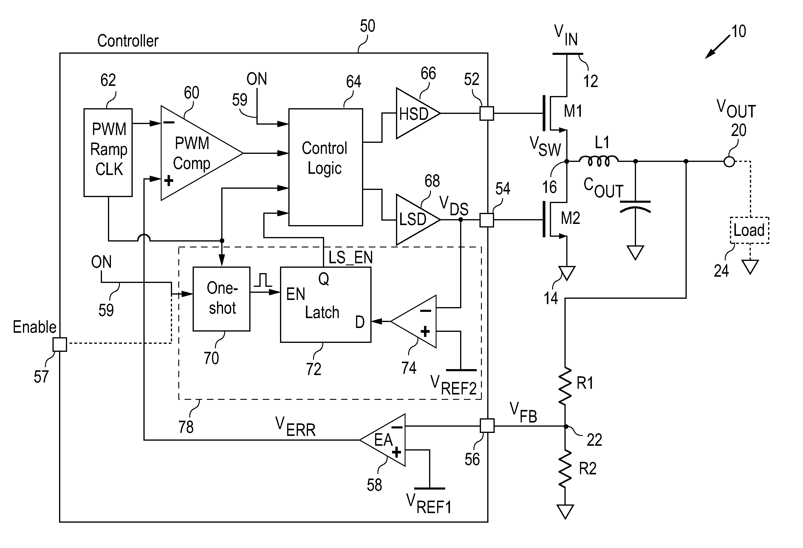
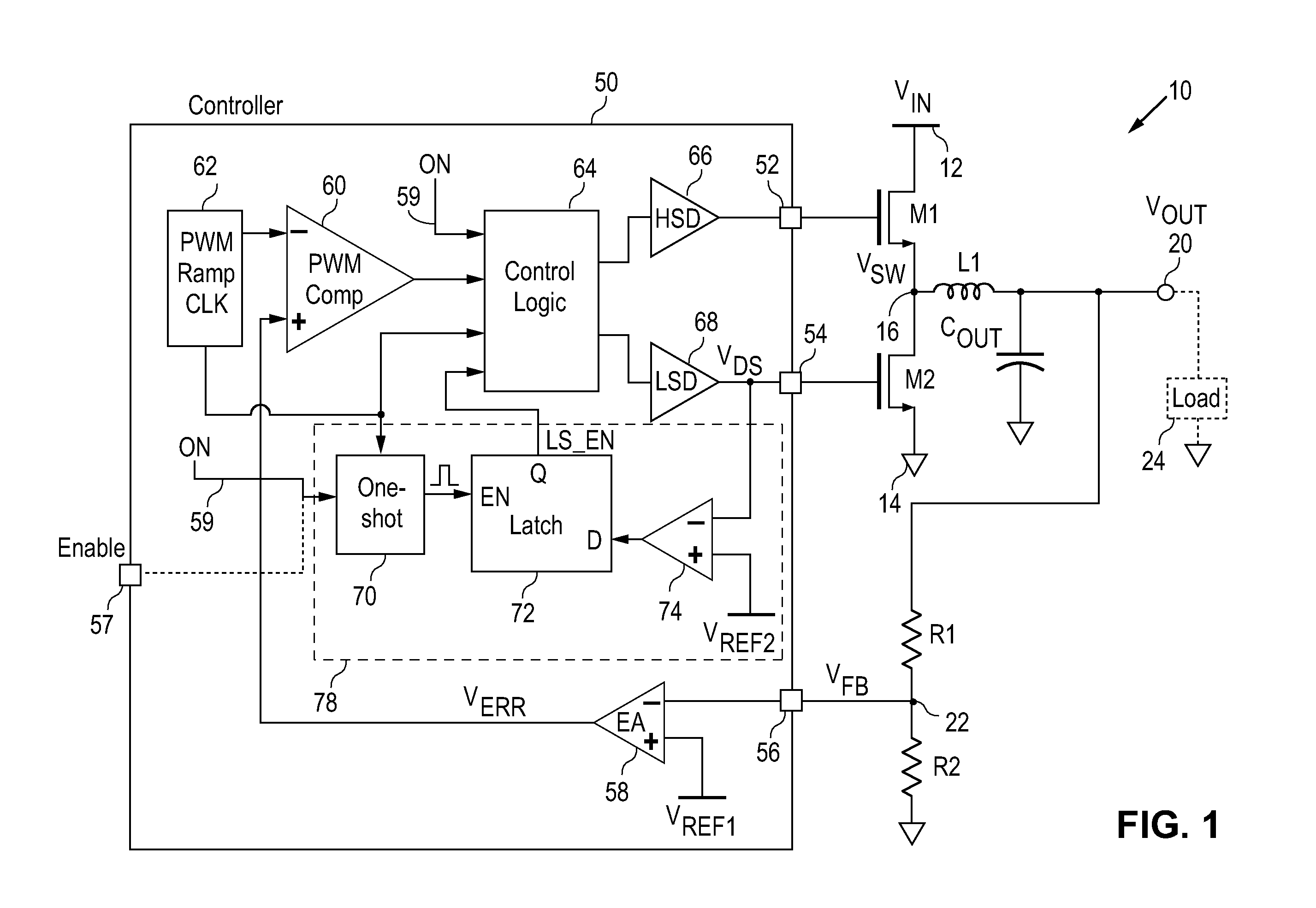
[0014]In accordance with the principles of the present invention, a synchronous switching regulator controller (“synchronous controller”) incorporates an automatic switch detection circuit to determine the presence or absence of a power switch at the output of the low-side switch driver so that the switch driver can be disabled when the low-side switch driver is not used to drive an active power switch. The automatic switch detection circuit of the present invention operates to prevent the synchronous switching regulator controller from switching an unused driver output node. In this manner, unwanted EMI noise emission from the controller is avoided.

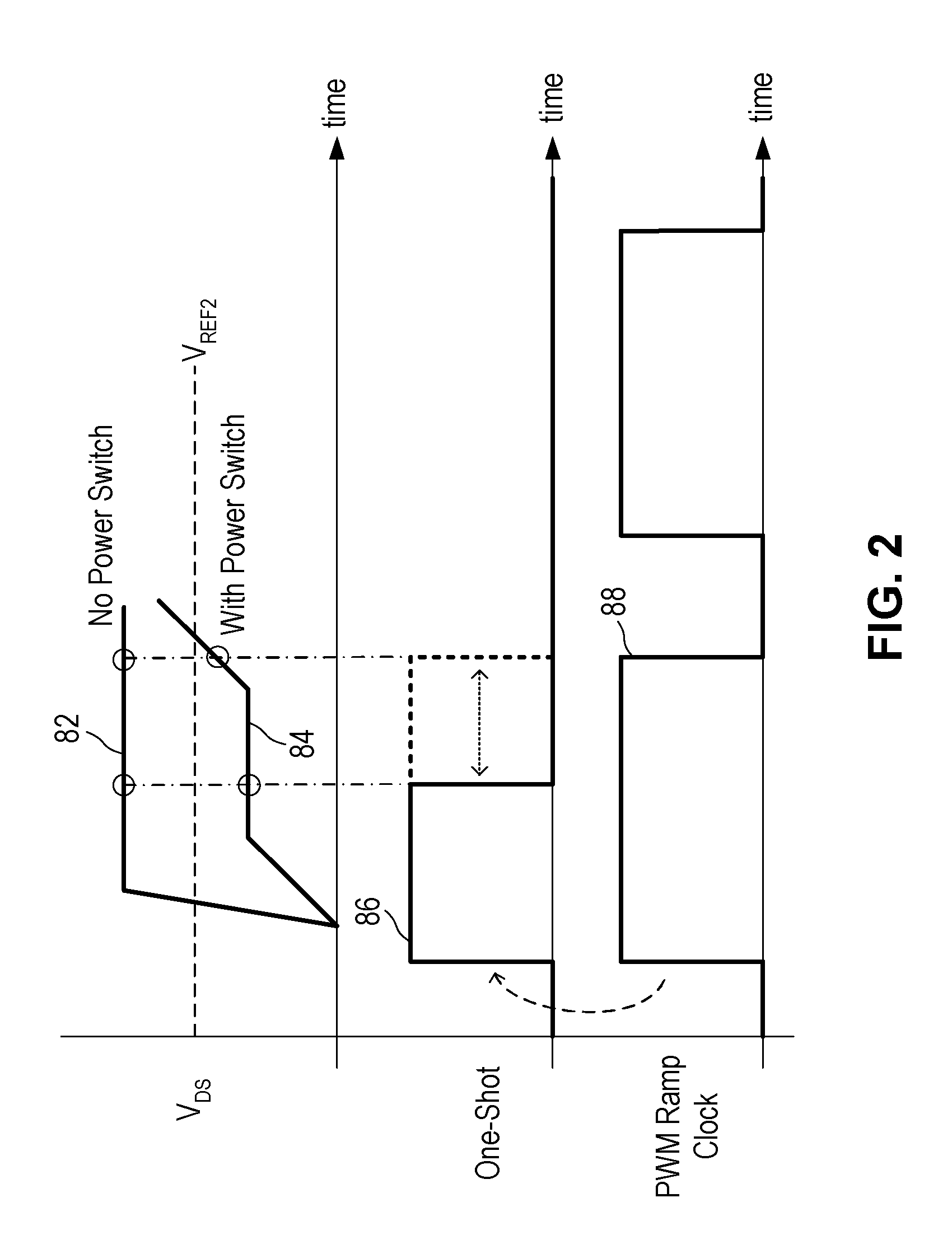
[0015]In operation, the input impedance of the power switch is used to indicate the presence of a power switch coupled to the low-side switch driver. The voltage value at the output node of the switch driver in response to a PWM pulse indicates either an open node or a node with a certain amount of input impedance. When the voltage of th...


PUM


Abstract

A synchronous switching regulator controller incorporates a switch detection circuit to determine the presence or absence of a power switch at the output of a switch driver so that the switch driver can be disabled when it is left unused. In one embodiment, the synchronous controller includes a switch detection circuit receiving a power cycle signal and the PWM ramp clock signal and measuring a voltage at an output node of the switch driver. The switch detection circuit provides a driver enable signal in response to the assertion of the power cycle signal. The driver enable signal has a first logical state when the voltage at the output node of the switch driver is greater than a reference voltage and a second logical state when the voltage at the output node is less than a reference voltage. The switch driver can be disabled based on the driver enable signal.

Description

FIELD OF THE INVENTION[0001]The invention relates to synchronous switching regulator controllers and, in particular, to a synchronous switching regulator controller with automatic external power switch detection.DESCRIPTION OF THE RELATED ART[0002]DC voltage regulators or switching regulators operate to convert energy from one DC voltage level to another DC voltage level. This type of switching regulators is also referred to as DC / DC converters. A switching regulator, sometimes referred to as a switching mode power supply, provides power supply function through low loss components such as capacitors, inductors, and transformers, and power switches that are turned on and off to transfer energy from the input to the output in discrete packets. A feedback control circuit is used to regulate the energy transfer to maintain a constant output voltage within the desired load limits of the circuit.[0003]A switching regulator can be configured to step up the input voltage or step down the in...

Claims


Application Information

Patent Timeline
IPC IPC(8): G05F1/00
CPCH02M3/157Y02B70/1466H02M3/1588Y02B70/10
Inventor KIM, SANG HOON
Owner MICREL
Why Eureka
Try Eureka