Apparatus for and method of measuring composition and pressure of the discharged gas from ion gauge using residual gas analyzer

a technology of residual gas analyzer and ion gauge, which is applied in the direction of fluid pressure measurement, fluid pressure measurement by electric/magnetic elements, instruments, etc., can solve the problems of inability to quantitatively know the type and volume of gas (i.e., pressure) discharged from the hot cathode ion gauge, and the difficulty of accurately measuring vacuum pressure, so as to prevent unexpected chemical reactions and improve the quality of fabricated products.

Inactive Publication Date: 2008-02-28
KOREA RES INST OF STANDARDS & SCI
View PDF10 Cites 12 Cited by
  • Summary
  • Abstract
  • Description
  • Claims
  • Application Information

AI Technical Summary

Benefits of technology

[0016]Second object of the present invention is to provide an apparatus for and method of measuring the composition and the pressure of the discharged gas from an ion gauge by using a residual gas analyzer, which enables to prevent unexpected chemical reaction in the process by measuring the kind and volume of the discharged gas, to protect devices of other process, and to improve the quality of the fabricated products.

Problems solved by technology

With regard to the conventional hot cathode ion gauge, several problems were existed as follows.
The gas discharged from the ion gauge 100 causes grounds of contaminating the vacuum container or increasing the pressure, so that it was difficult to measure the vacuum pressure accurately.
By this time, it was impossible to anticipate the effect of the gas, because it was impossible to know the kind and volume of the gas (i.e., pressure) discharged from the hot cathode ion gauge quantitatively.
Especially, because the gas discharged from the ion gauge, which was indispensable to measure the ultra high vacuum in the high-tech vacuum processes such as those employed in the fabrication of the semiconductor or the display, reacted with other gas in the process or increased the pressure of the gas, so that these gases caused grounds of reducing the capacity or the durability of the products.

Method used


Image

  • Apparatus for and method of measuring composition and pressure of the discharged gas from ion gauge using residual gas analyzer
  • Apparatus for and method of measuring composition and pressure of the discharged gas from ion gauge using residual gas analyzer
  • Apparatus for and method of measuring composition and pressure of the discharged gas from ion gauge using residual gas analyzer

Examples


Embodiment Construction

[0039]Reference will now be made in detail to the preferred embodiment of the present invention with reference to the attached drawings.

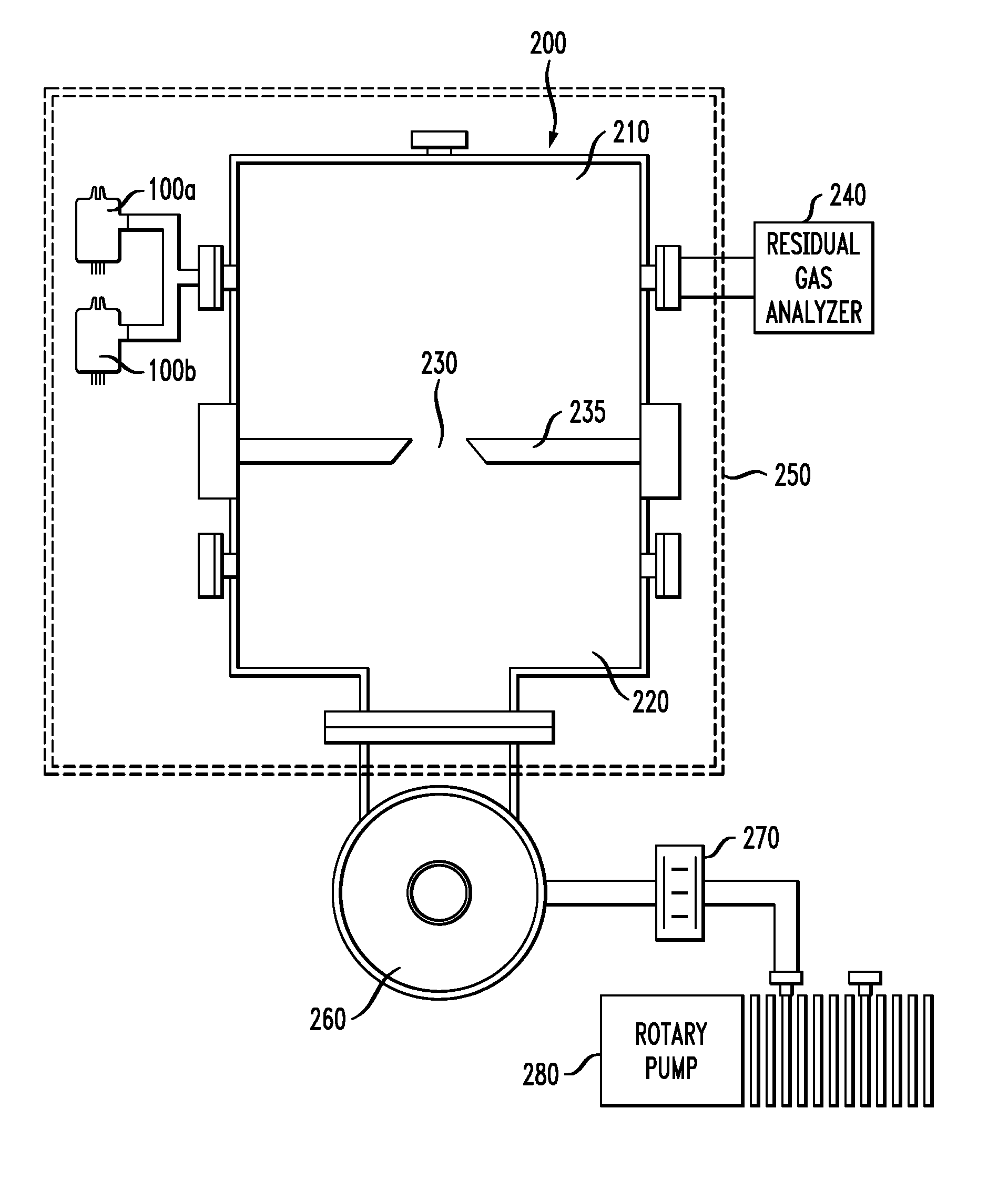
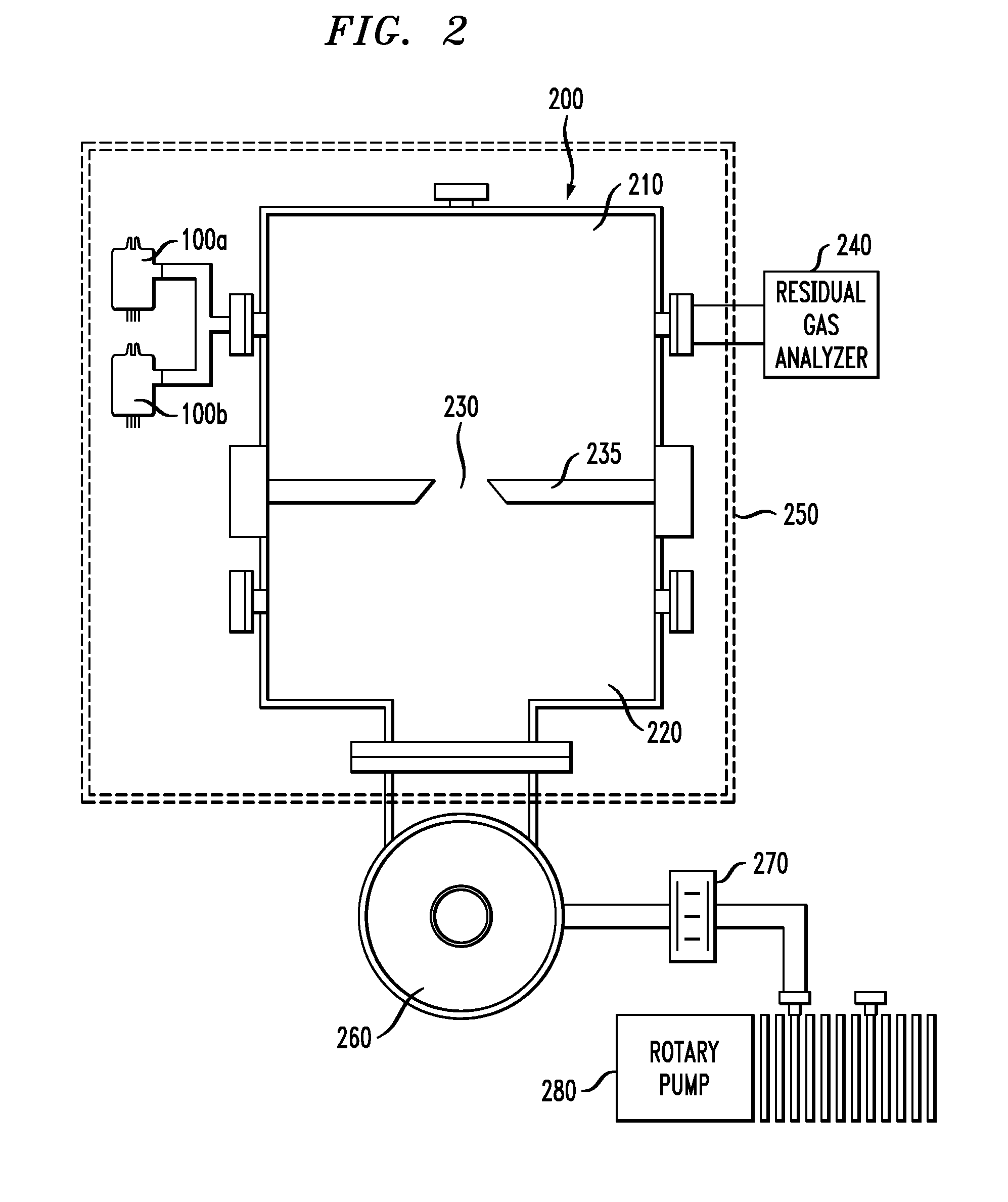
[0040]FIG. 2 is a schematic cross-sectional view showing the apparatus for measuring the composition and the pressure of the discharged gas according to the present invention. As shown in FIG. 2, the constitution of the present invention can be largely divided into a vacuum container 200 and peripherals.

[0041]The vacuum container 200 is made of stainless steel material in order to prevent the discharge of the gas and is formed of cylindrical shape having a diameter of about 250 mm. The inside of the vacuum container 200 is divided into an upper pressure container 210 and a lower discharge container 220 by means of a partition 235. The partition 235 is made of stainless steel material as is the vacuum container 200, and is formed with an orifice 230 penetrating through the center thereof and with a diameter of about 10 mm. When the diameter of the or...


PUM

PropertyMeasurementUnit
pressureaaaaaaaaaa
pressureaaaaaaaaaa
diameteraaaaaaaaaa

Abstract

Disclosed herein are an apparatus for and method of measuring the composition and the pressure of the discharged gas from an ion gauge by using a residual gas analyzer. In this regard, there are provided a vacuum container 200 divided into a pressure container 210 and a discharge container 220 by means of a partition 235 having an orifice 230 formed thereon; an ion gauge 100 mounted at the pressure container 210 side of the vacuum container 200 for discharging the gas at the time of vacuum formation; a residual gas analyzer 240 mounted at the pressure container 210 side of the vacuum container 200 for measuring the composition and the pressure of the residual gas; pump means disposed at one side of the discharge container 220 of the vacuum container 200 for discharging the inside gas; and heating means disposed at the vacuum container 200 for heating the vacuum container 200 to a predetermined temperature.

Description

BACKGROUND OF THE INVENTION[0001]1. Field of the Invention[0002]The invention relates to an apparatus for and method of measuring the composition and the pressure of the discharged gas from a hot cathode ion gauge mounted to a container of an ultra high vacuum (<10−7 Pa) using a residual gas analyzer.[0003]2. Background of the Related Art[0004]In general, an ion gauge employed in the high-tech display or semiconductor fabrication process is a pressure sensor, which is used in the measurement of the pressure in high vacuum or ultra high vacuum.[0005]FIG. 1 is a schematic cross-sectional view showing the principle of a hot cathode ion gauge used in the present invention. As shown in FIG. 1, a main body 106 is formed of transparent glass or metal material, and a filament 104 is provided at the inside thereof.[0006]A vacuum port 112 is a constitutional portion to be connected to a pressure container 210, and an ion collector 108 is hanged by extension from the upper portion of the ce...

Claims


Application Information

Patent Timeline
Patent Type & Authority Applications(United States)
IPC IPC(8): G01N27/62
CPCG01L21/34G01D21/02G01L9/0091G01L21/32
Inventor HONG, SEUNG SOOCHUNG, KWANG HWASHIN, YONG HYEON
Owner KOREA RES INST OF STANDARDS & SCI
Why Eureka
Try Eureka