Power supply controller

Active Publication Date: 2008-02-28
AUTONETWORKS TECH LTD +2
View PDF5 Cites 26 Cited by
  • Summary
  • Abstract
  • Description
  • Claims
  • Application Information

AI Technical Summary

Benefits of technology

[0036]In the case that the load is a motor, the predetermined time may be set to a larger value, so that a short anomaly can be determined after variation of the output termin

Problems solved by technology

Further a problem arises that the self-protective function will not operate due t

Method used


Image

  • Power supply controller
  • Power supply controller
  • Power supply controller

Examples


Example

[0051]A first embodiment of the present invention will be explained with reference to FIGS. 1 through 11. In the drawings, an overbar attached to a symbol indicating each of various signals represents that the signal is a low active signal.

[0052]1. Construction of Power Supply Controller

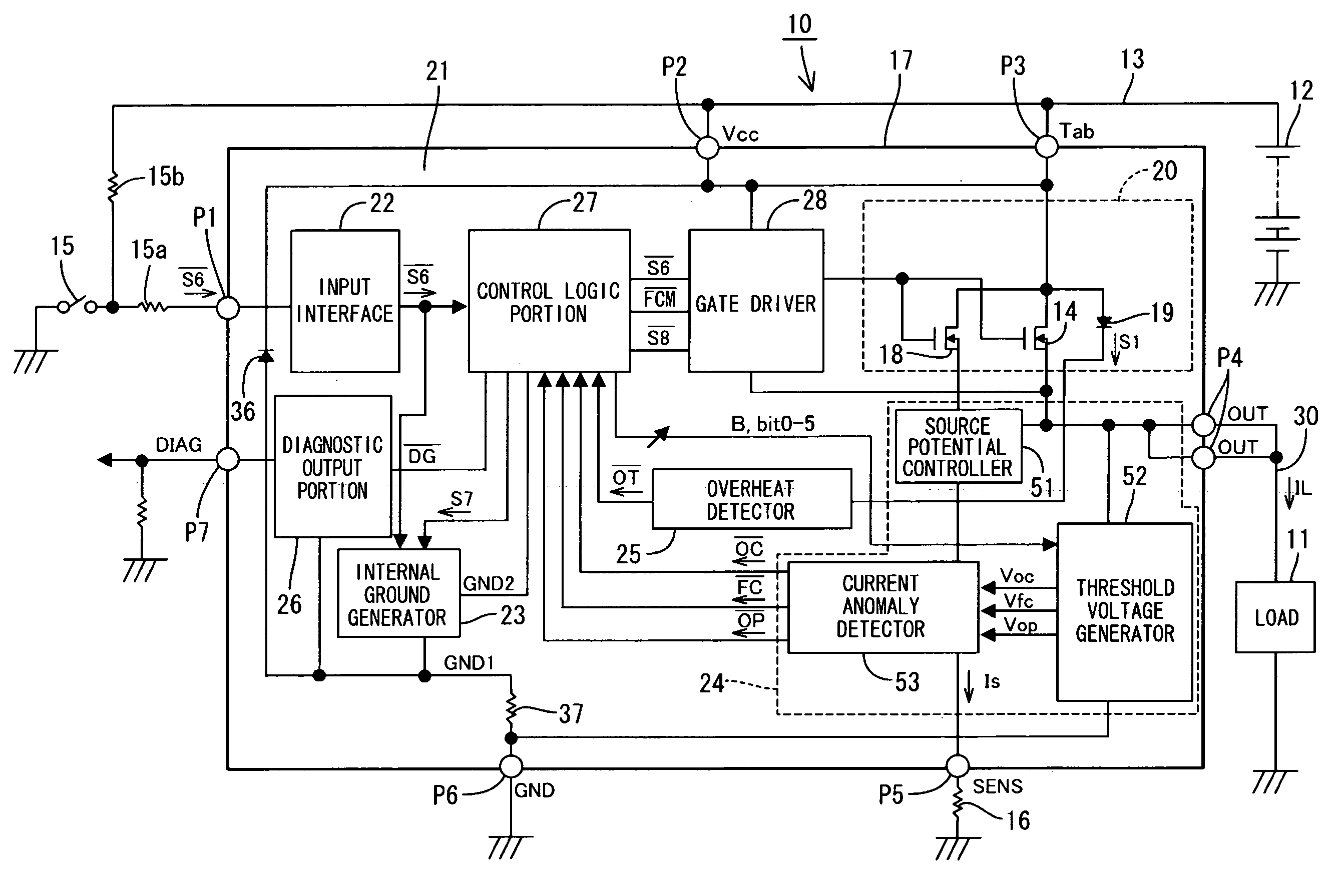
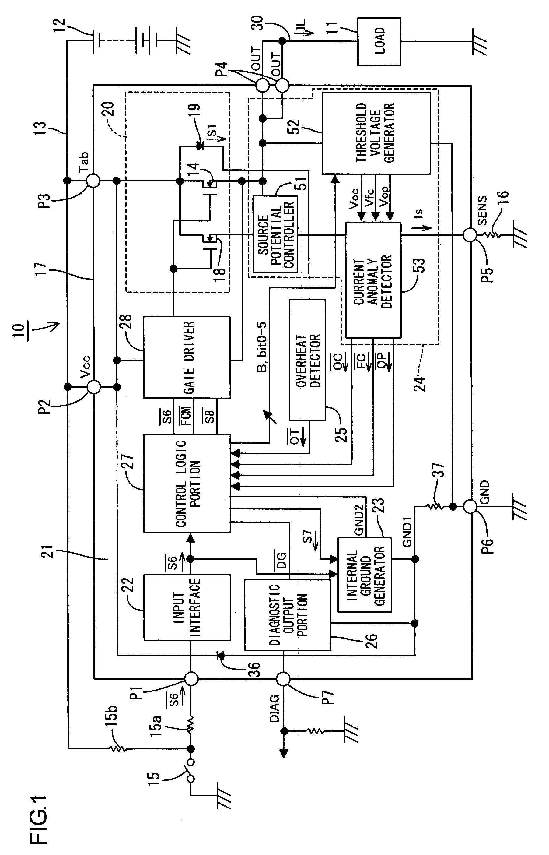
[0053]FIG. 1 is a block diagram showing the general construction of a power supply controller according to the present embodiment. The power supply controller can be installed on a vehicle (not shown), and used for controlling power supply from a vehicle power source 12 (hereinafter referred to as a power source) to a load 11 such as a defogger heater (i.e., a linear resistive load), a vehicle lamp or a motor (i.e., an L-load or inductive load) for a cooling fan or a wiper.

[0054]Hereinafter, the “load” means a device to be controlled by the power supply controller 10, and does not include an electric wire 30 connected between the power supply controller 10 and the controlled device. The load 11 and t...

Example

Second Embodiment

[0328]Next, a second embodiment of the present invention will be explained with reference to FIGS. 12 and 13.

[0329]In the first embodiment shown in FIGS. 1 through 11, whether the power MOSFET 14 is in an ON state or not is determined based on the gate-to-source voltage Vgs of the power MOSFET 14. In contrast, according to the present embodiment, whether the power MOSFET 14 is in an ON state or not is determined based on the source voltage Vs′ of the sense MOSFET 18.

[0330]The other constructions of the present embodiment are similar to the first embodiment. Therefore the same components as the first embodiment are designated by the same symbols, and redundant explanation is omitted. The difference from the first embodiment is as follows.

[0331]According to the present embodiment, a second determination circuit 122 determines whether the power MOSFET 14 is in the ON state or not based on the source voltage Vs′ of the sense MOSFET 18 as shown in FIG. 12. The source vol...


PUM


Abstract

A power supply controller includes a semiconductor switching element disposed on a current supply line from a power source to a load. The semiconductor switching element is switched between ON and OFF for controlling power supply to the load. A short anomaly of the semiconductor switching element is determined if at least one of an input-to-output voltage of the semiconductor switching element being smaller than a first threshold and the semiconductor switching element being in an ON state is detected, when an OFF signal for instruction to turn OFF the semiconductor switching element is received.

Description

CROSS REFERENCE TO RELATED APPLICATION[0001]The present application claims priority from Japanese Patent Application No. 2006-190703 filed on Jul. 11, 2006. The entire content of this priority application is incorporated herein by reference.BACKGROUND OF THE INVENTION[0002]1. Field of the Invention[0003]The present invention relates to a power supply controller, and particularly relates to detection of a short-circuit anomaly of a semiconductor switching element.[0004]2. Description of the Related Art[0005]A power supply controller is conventionally provided for controlling power supply to a load. In the power supply controller, a high-power semiconductor switching element such as a power MOSFET is disposed on a current supply line connected between a power source and the load, and the power supply to the load is controlled by switching the semiconductor switching element between ON and OFF according to external ON and OFF signals.[0006]In such a power supply controller, it is known...

Claims


Application Information

Patent Timeline
IPC IPC(8): G08B21/00
CPCH03K17/0822H03K2017/0806H03K17/60H03K17/18
Inventor TAKAHASHI, SEIJI
Owner AUTONETWORKS TECH LTD
Why Eureka
Try Eureka