Screen and projector

Inactive Publication Date: 2008-02-28
COLUMBIA PEAK VENTURES LLC
View PDF10 Cites 18 Cited by
  • Summary
  • Abstract
  • Description
  • Claims
  • Application Information

AI Technical Summary

Benefits of technology

[0023] In the screen described above, the moving means preferably moves the first or second layer in the direction substantially parallel to the layer that faces the moving layer. In this way, the first or second layer or the first and second layers moved by the moving means can move while preventing a gap between the two layers from increasing, suppressing reduction in image quality, such as image blur, associated with

Problems solved by technology

In JP-A-2005-107150, the configuration of the screen is not clearly described and change in refraction position means change in focus position, disadvantageously resulting in less accurate focusing.
In JP-A-2001-100316, when a light diffusion layer

Method used


Image

  • Screen and projector
  • Screen and projector
  • Screen and projector

Examples


first embodiment

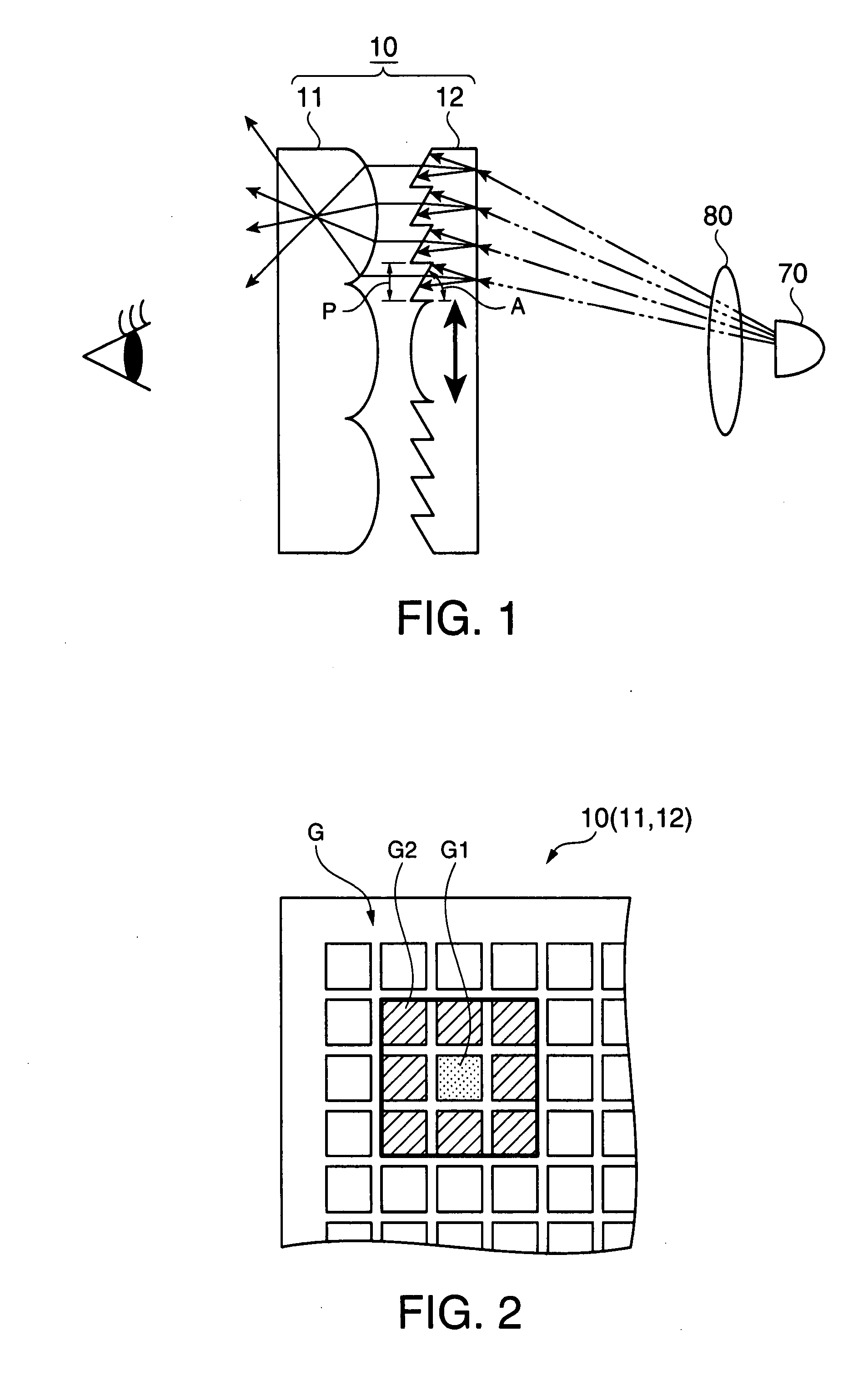
[0028]FIG. 1 is a schematic view showing the relationship between the screen according to a first embodiment of the invention and incident light. FIG. 2 is a schematic view showing the extent within which a second layer moves. FIG. 3 is a schematic view showing the relationship between the motion of the second layer and a speckle pattern generated on the screen. The configuration and operation of the screen 10 will be described with reference to FIGS. 1 to 3.

[0029] As shown in FIG. 1, the screen 10 in this embodiment includes a first layer having viewing angle control means for enlarging the viewing angle and a second layer having angular conversion means for converting the angles of incidence of incident light beams into the substantially same direction. One of the layers has a diffusion capability to diffuse incident light beams. As for the motion of the first and second layers, the one of the layers having the diffusion capability has moving means and moves relative to the other...

second embodiment

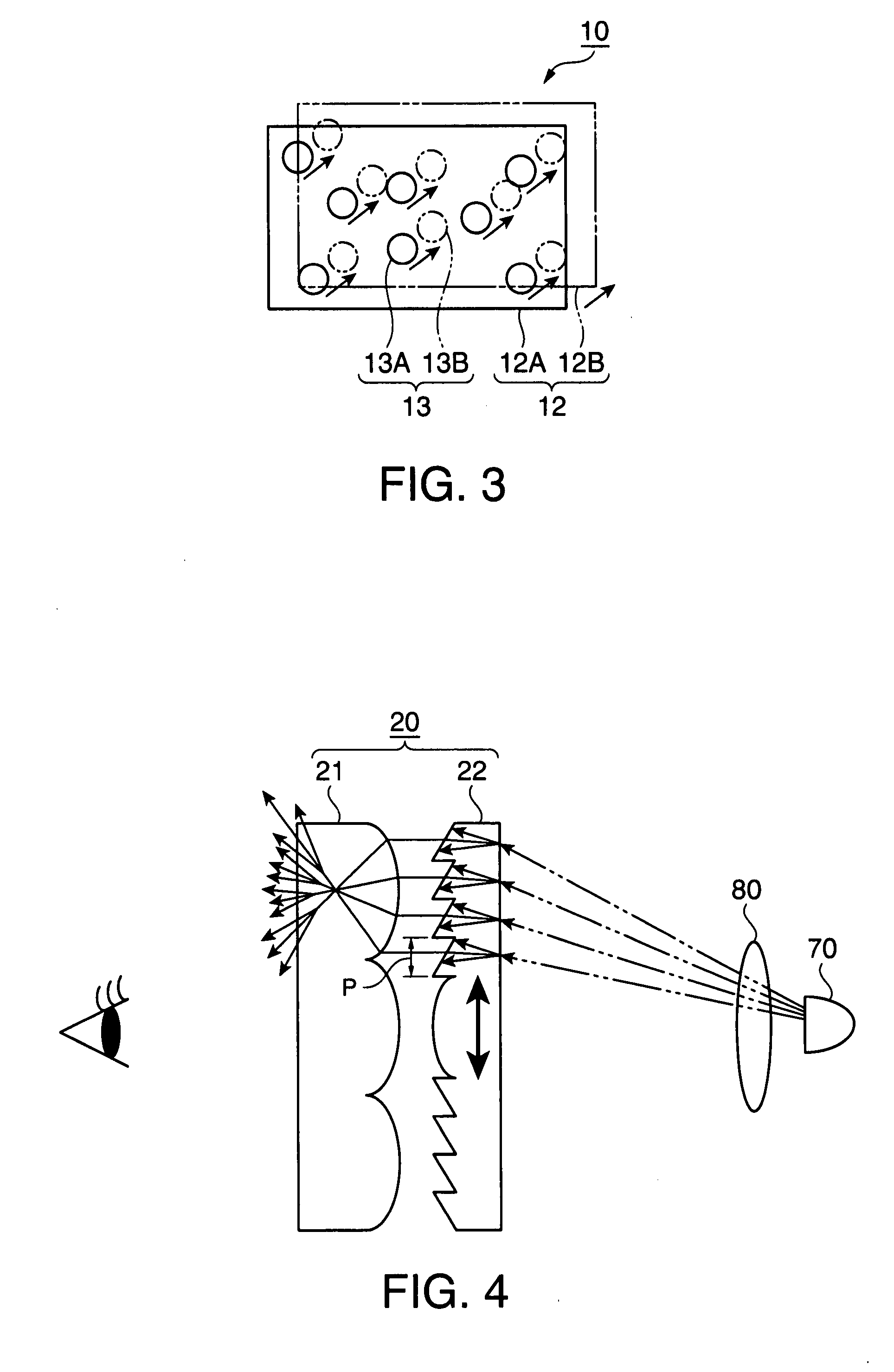
[0053]FIG. 4 is a schematic view showing the relationship between the screen according to a second embodiment of the invention and incident light. The configuration and operation of the screen 20 will be described with reference to FIG. 4.

[0054] As shown in FIG. 4, the screen 20 has the substantially same configuration as that of the screen 10 in the first embodiment except that in the first embodiment, the second layer has the diffusion capability and moves relative to the first layer with no diffusion capability, while in the second embodiment, the first and second layers both have diffusion capabilities. As for the motion of the first and second layers, at least one of the layers moves relative to the other.

[0055] Specifically, the configuration in this embodiment includes a lenticular lens 21 as the first layer having viewing angle control means for enlarging the viewing angle and a Fresnel lens 22 as the second layer having angular conversion means for converting the angles o...

third embodiment

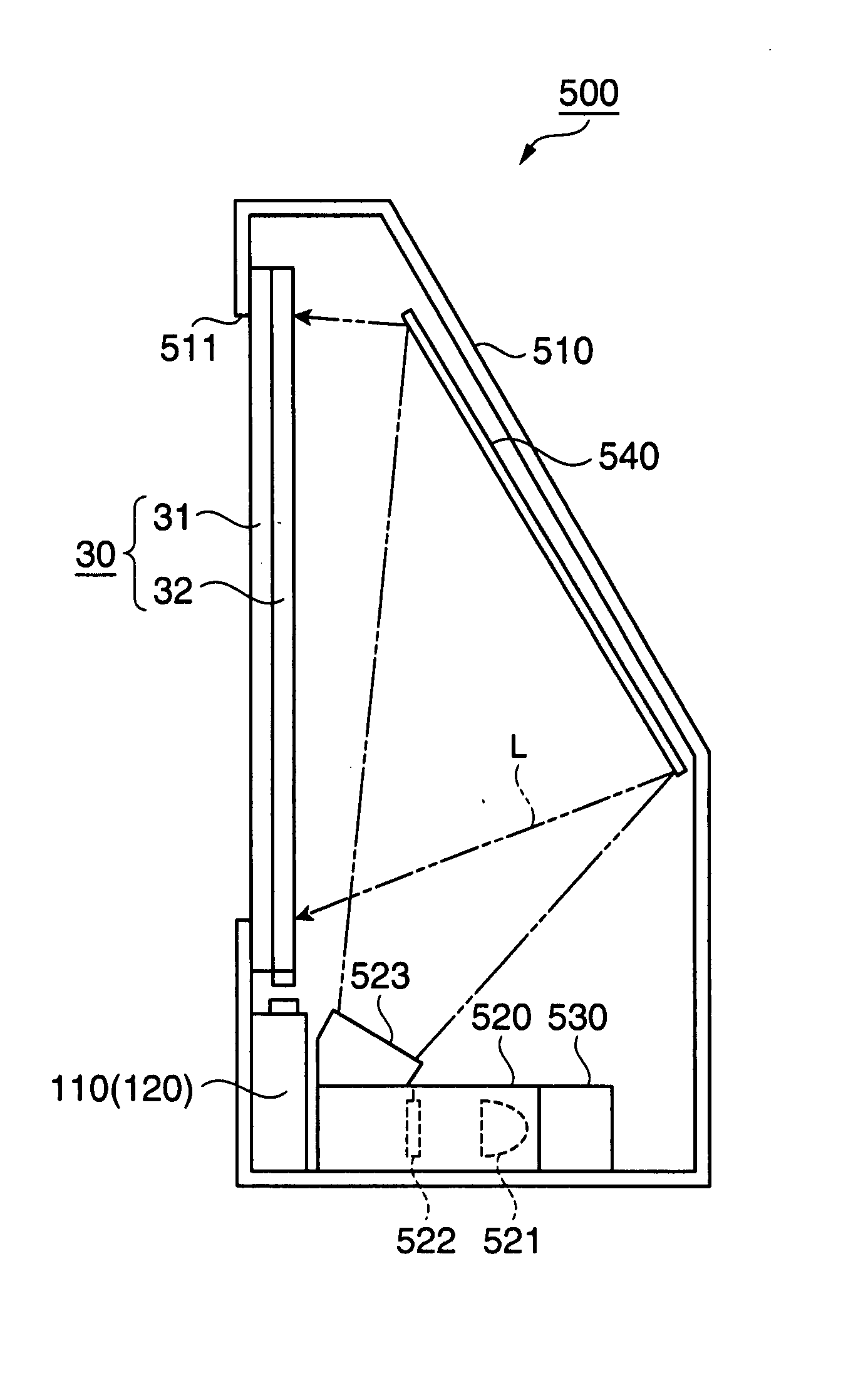
[0070]FIG. 5 is a schematic side cross-sectional view when the screen according to a third embodiment of the invention is applied to a rear projector. FIG. 6 is a schematic configuration diagram of the screen having moving means.

[0071] The configuration and operation of a rear projector 500 as a projector will be schematically described with reference to FIG. 5.

[0072] As shown in FIG. 5, the rear projector 500 generally includes a cabinet 510 as an external housing, a projector unit 520 as an image projection device, a control unit 530, a reflective mirror 540, a transmissive screen 30, a control circuit 110 that is a component of moving means, and a driver 120.

[0073] The cabinet 510 has a box shape with its back side (right side in FIG. 5) inclined and houses the projector unit 520, the control unit 530, and the reflective mirror 540 therein, as shown in FIG. 5. Although not specifically illustrated, the cabinet 510 houses a power supply unit that supplies power to various compo...


PUM


Abstract

There is provided a screen and a projector using a simple configuration and operation to make speckles less visible. A screen 10 on which light beams are incident includes a lenticular lens 11 as a first layer having viewing angle control means for enlarging the viewing angle and a Fresnel lens 12 as a second layer having angular conversion means for converting the angles of incidence of the incident light beams into the substantially same direction. One of the first and second layers has a diffusion capability that diffuses the incident light beams and has moving means for moving that layer relative to the other. Alternatively, the first and second layers both have the diffusion capability, and at least one of the layers has moving means for moving that layer relative to the other.

Description

BACKGROUND OF THE INVENTION [0001] The present invention relates to a screen on which light beams are incident and a projector that projects an optical image onto the screen. [0002] A conventional projector that projects an optical image onto a screen, such as a rear projector, increasingly has a larger screen and higher resolution (a rear projector is an apparatus including a projector and a screen, both housed in a housing, and projecting images from the projector onto the screen to allow a viewer to look at the images passing through the screen). In such circumstances, the glare (so-called scintillation) generated on the screen has been a problem. Scintillation results from intensity (brightness) unevenness of light called speckles generated when the wavelengths of light beams that exit from the screen interfere with each other. [0003] JP-A-2005-107150 discloses an apparatus for reducing generation of speckles by pneumatically or electrically oscillating at least one of two or mo...

Claims


Application Information

Patent Timeline
IPC IPC(8): G03B21/62G03B21/00G03B21/10G03B21/625H04N5/74
CPCG03B21/62
Inventor MORIKUNI, EIJISHINBO, AKIRASEKI, HIDEYA
Owner COLUMBIA PEAK VENTURES LLC
Why Eureka
Try Eureka