
High voltage output device and ion generator provided therewith

a high-voltage output and ion generator technology, which is applied in the direction of discharge tube ion guns, electrostatic charges, electrical apparatus, etc., can solve the problems of remarkable output voltage drop, reduced circuit efficiency, and reduced output voltage on the secondary side of pulse transformer pt, so as to achieve high-voltage output voltage efficiently

Inactive Publication Date: 2008-02-28
SHARP KK
View PDF0 Cites 5 Cited by
  • Summary
  • Abstract
  • Description
  • Claims
  • Application Information

AI Technical Summary

Benefits of technology

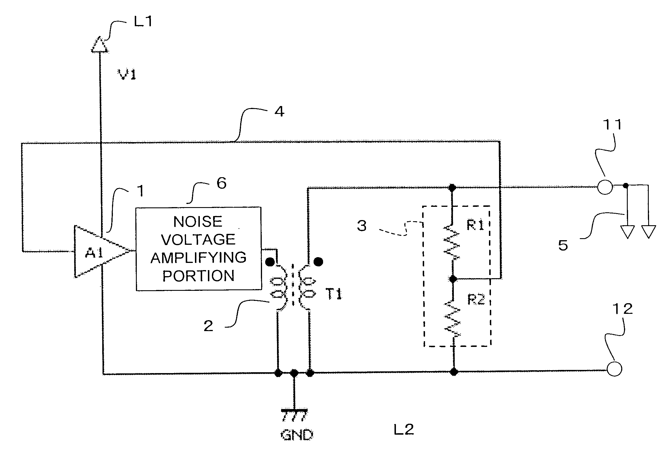
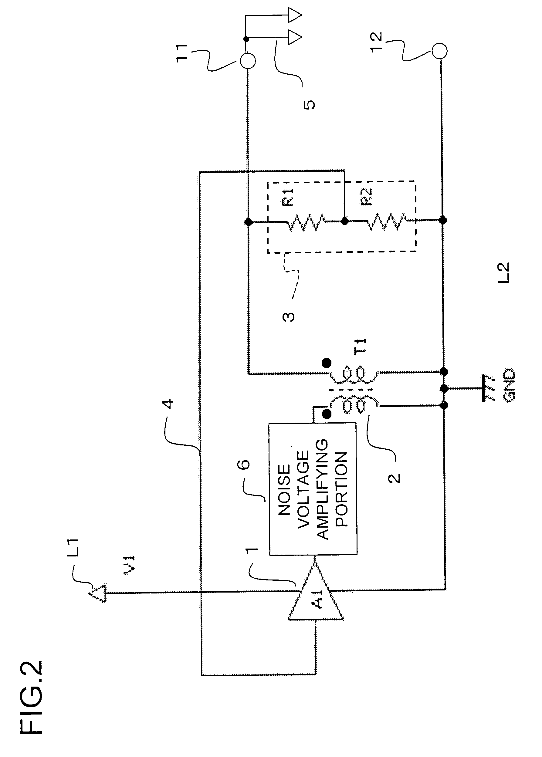
[0021]According to such a configuration as described hereinabove, since a voltage being produced from the secondary side of a transformer is fed back, a signal (a voltage) corresponding to a frequency of the voltage can be fed to the primary side of the transformer. Therefore, for example, when a resonance circuit is formed by having a capacitive load connected to the secondary side of the transformer, it is easy to practically offer a high voltage output device of high efficiency that can follow fluctuations in the resonance frequency (for example, due to a fluctuation in the capacitive load being connected to the secondary side of the transformer) if any. To be specific, by forming a resonance circuit system including the primary side and the secondary side of the transformer, it becomes easy to prevent a difference (deviation) between a voltage being fed from the primary side of the transformer and a resonance frequency on the secondary side of the transformer from occurring.
[0088]In addition, when an electronic apparatus is a thermometer unit that comprises a thermometer, and a container in accordance with the above-mentioned configuration for housing the thermometer inside thereof (Forty-First Configuration), it is easy to maintain the thermometer, which is one of clinical instruments, in a hygienic condition.

Problems solved by technology

And, when the resonance frequency on the secondary side of the pulse transformer differs from the frequency of the alternate current voltage being fed to the pulse transformer PT, which is, specifically, the output frequency of the oscillation circuit MV, the output voltage on the secondary side of the pulse transformer PT is decreased, whereby the efficiency of the circuit is reduced, which provides a problem.
A problem of a decrease in the output voltage becomes remarkable when the value of “L” is large and the value of “C” is small.
Specifically, there is a problem that the efficiency is deteriorated.
Especially, when it is intended to produce a high voltage in a transformer, the above-mentioned value of “L” becomes large due to an increase in the winding number of a coil on the secondary side of the transformer, and as a result, a problem of a decrease in the output voltage due to a deviation of the frequency becomes remarkable.
Therefore, there exists a problem that an amount of ion generation is reduced to be a half or less.

Method used


Image

  • High voltage output device and ion generator provided therewith
  • High voltage output device and ion generator provided therewith
  • High voltage output device and ion generator provided therewith

Examples


first embodiment

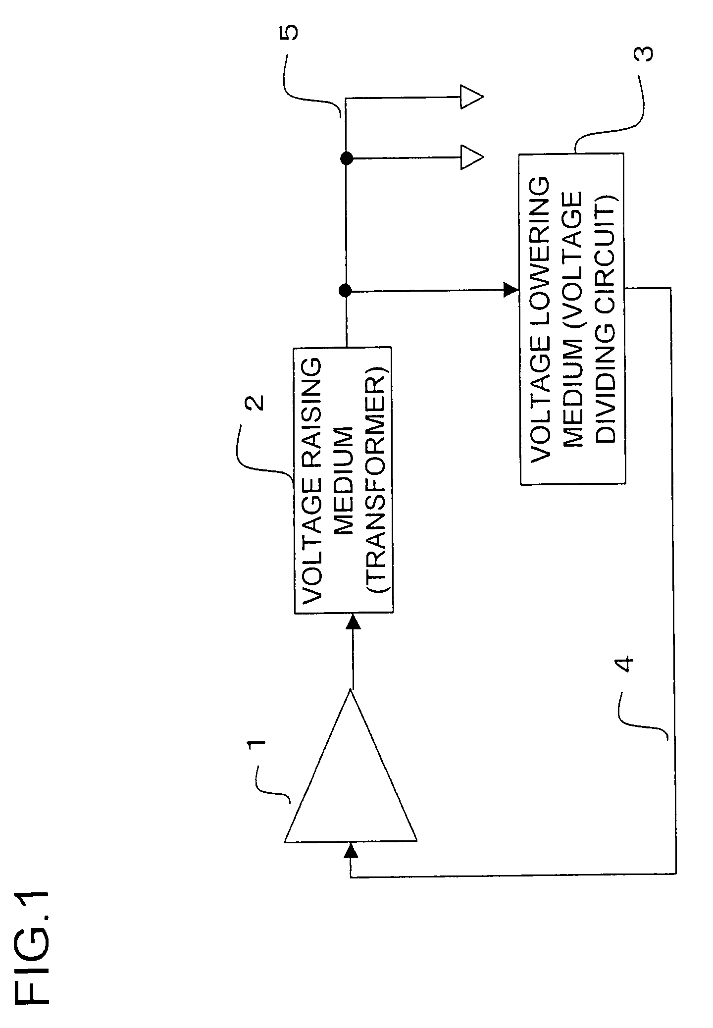
[0115]By referring to the drawings, a first embodiment of an ion generator in accordance with the present invention will be described hereinafter. FIG. 1 is a block diagram showing an overview of an ion generator in accordance with the present embodiment of the present invention.

[0116]An ion generator shown in FIG. 1 comprises an alternate signal amplifying medium 1; a winding transformer (a voltage raising medium) 2; a voltage lowering medium (a voltage dividing circuit) 3; a feedback circuit 4; and ion generating elements 5, and the like. An ion generator that has ion generating elements 5 excluded can be regarded as a high voltage output device that feeds a high voltage to a secondary side of the winding transformer 2. “A high voltage” herein means a voltage that is as high as a voltage at which ions are generated from the ion generating elements 5 when a voltage is applied to the ion generating elements 5, and a level of such a voltage (in an absolute value) is, for example, mor...

second embodiment

[0151]By referring to the drawings, a second embodiment of an ion generator in accordance with the present invention will be concretely described hereinafter. Basically, the present embodiment has a same configuration as the first embodiment, excluding a point that an alternate current signal producing medium 101 is provided in place of an alternate current signal amplifying medium 1, so that overlapped description will be omitted.

[0152]FIG. 7 is a block diagram showing an overview of an ion generator in accordance with the present embodiment. As shown in this figure, an ion generator comprises an alternate current signal producing medium 101, a winding transformer (a voltage raising medium) 2, a voltage lowering medium (a voltage dividing circuit) 3, a feedback circuit 4, and ion generating elements 5, and the like. To be specific, instead of the alternate current signal amplifying medium 1 in accordance with the first embodiment, the alternate current signal producing medium 101 i...

third embodiment

[0176]The ion generator in accordance with the above-mentioned first embodiment can adjust the output voltage to the ion generating elements 5 by adjusting the level of the supply voltage V1 to the alternate signal amplifying medium 1; and the ion generator in accordance with the second embodiment can adjust the output voltage to the ion generating elements 5 by adjusting the level of the supply voltage V1 to the alternate signal producing medium 101. Therefore, the ion generators in accordance with the first and the second embodiments can generate not only the ions but also the ozone, by adjusting the level of the supply voltage V1, whereby the ion generators can serve as an ion / ozone generator

[0177]Now, a third embodiment in accordance with the present invention will be described hereinafter by referring to an ion / ozone generator. First, FIG. 4 shows an example of a diagram indicating a relationship between the voltage between the ion generating elements (or the voltage amplificat...


PUM


Abstract

A high voltage output device in accordance with the present invention, which comprises a transformer that amplifies a voltage being fed to a primary side coil thereof so as to be produced from a secondary side coil thereof, and in which an alternate current input voltage is fed from the primary side coil, and an output voltage is taken out from the secondary side coil, further comprises a feedback circuit that feeds back the output voltage, and a voltage amplifying circuit that amplifies the voltage being fed back so as to be fed to the primary side coil. As a result, it is possible to provide such a high voltage output device as can obtain an output voltage efficiently, although a load capacity on a secondary side of a transformer fluctuates.

Description

CROSS-REFERENCE TO RELATED APPLICATIONS[0001]This application is based on Patent Application No. 2006-197115 being filed in Japan on Jul. 19, 2006, Patent Application No. 2006-315255 being filed in Japan on Nov. 22, 2006 and Patent Application No. 2007-095333 being filed in Japan on Mar. 30, 2007, the entire contents of which are hereby incorporated by reference.BACKGROUND OF THE INVENTION[0002]1. Field of the Invention[0003]The present invention relates to a high voltage output device that produces a high voltage by employing a transformer, and relates to an ion generator being provided with such a high voltage output device as has been mentioned. The present invention also relates to an electronic apparatus and the like being provided with such an ion generator.[0004]2. Description of the Prior Art[0005]Conventionally, in order to improve health and eliminate various bacteria from the atmosphere, there have been developed ion generators that generate negative ions or positive ions...

Claims


Application Information

Patent Timeline
Patent Type & Authority Applications(United States)
IPC IPC(8): H01J3/04
CPCH01T23/00
Inventor IKEDA, MASAKAZUEHIRO, MASAYUKIYAMASHITA, ATSUSHIYOSHIDA, SHINICHIYUMOTO, MANABU
Owner SHARP KK
Learn More