Joint Structure Between the Wall Elements of a Magnetically Shielded Room

a magnetic shielding room and joint structure technology, applied in the direction of couplings, electrically conductive connections, rod connections, etc., can solve the problems of plate thickness and profile not being completely uniform, and achieve the effect of improving contact, eliminating weakening effect on functioning, and improving electrical conta

Active Publication Date: 2008-02-28
MEGIN OY +1
View PDF11 Cites 16 Cited by
  • Summary
  • Abstract
  • Description
  • Claims
  • Application Information

AI Technical Summary

Benefits of technology

[0015] The physical dimensions of the plates have given tolerances, resulting in practice in that the plates and the profiles are not of completely uniform thickness. As two elements of non-uniform thickness are pressed against one another, they cause compression in the joint between them that is rather dot-like than continuous. This harmful phenomenon is eliminated when using presser rubbers to balance the pressing force over the entire joint area. In a preferred embodiment of the present invention, the presser rubber has a lightened cross section on the one side or both sides so that the spring constant associated with the compression of the presser rubber is smaller than that of the equal-thick rubber moulding. The lightening of the presser rubber can be implemented by shaping the profile to be wavy on either sides or both sides. In the present invention, the profiled presser rubber is placed on top of each μ metal moulding.
[0016] In the present invention, the electrical contact between the thinner aluminum plates is made over the joint by using supporting profiles, which are made, for example, from aluminum. Further, the supporting profile makes the joint more robust, providing the joint with a practical edge through which to fasten a bolt. A bolt and a threaded moulding can act to achieve the necessary compression in the joint. Instead of a threaded moulding, it is also possible to use a nut and a base plate.
[0017] The notch in the aluminum plates is made to be such that the plat

Problems solved by technology

The physical dimensions of the plates have given tolerances, resulting in pract

Method used


Image

  • Joint Structure Between the Wall Elements of a Magnetically Shielded Room
  • Joint Structure Between the Wall Elements of a Magnetically Shielded Room

Examples


Embodiment Construction

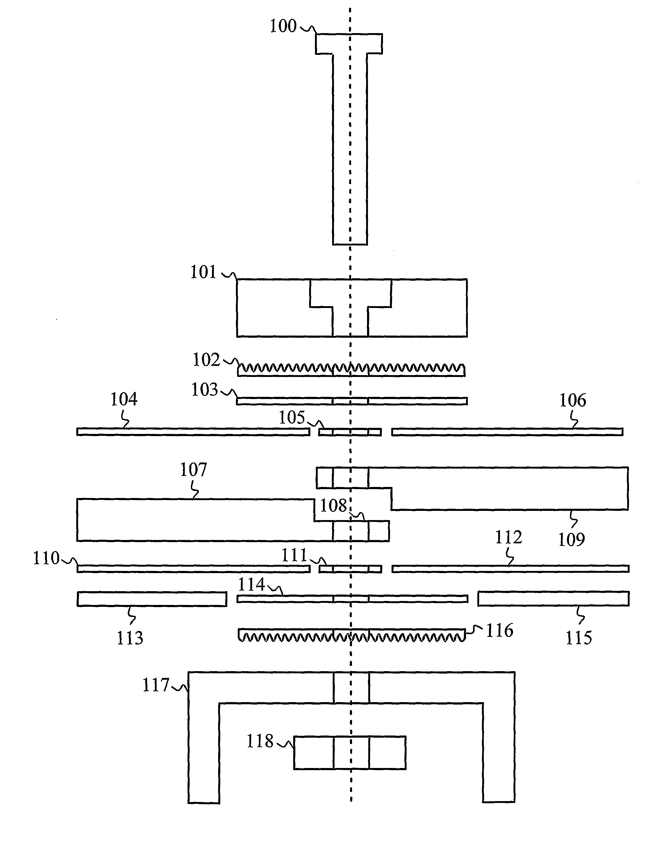
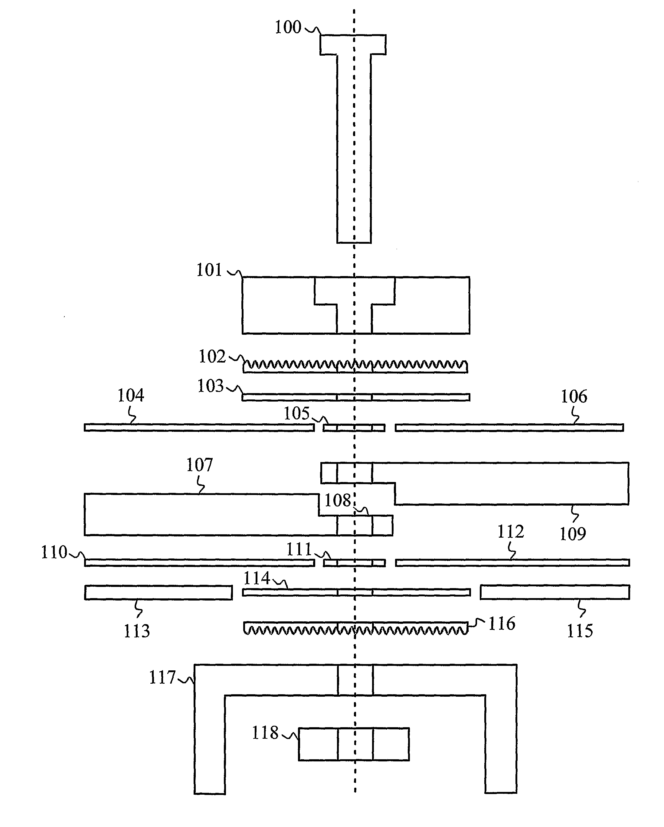
[0021] The present invention discloses a joint structure between the wall elements of a magnetically shielded room. The cross section of the joint structure is shown in FIG. 1.

[0022] The joint structure is associated specifically with the structure of a so-called lightweight shielded room. A lightweight shielded room is a shielded room shielding against magnetic interferences and consisting of elements that can be built on site about the measuring devices. The joint structure is used to join together two so-called sandwich elements. One wall element consists of a thick aluminum plate 107, coated e.g. with tin, of an inner μ metal plate 104, of an outer μ metal plate 110 and of a thin aluminum plate 113. An inner plate is herein used to mean a plate that is disposed closer to the measuring equipment to be shielded with the elements and at the same time closer to the inside of the shielded room. When examining the plate structure from the inside of the shielded room to the outside, t...


PUM


Abstract

The present invention discloses a joint structure between the wall elements of a light-weight magnetically shielded room. In the joint structure, the end of the aluminum plate of the element is stepped and its surface roughened. In addition to this, the aluminum plate is coated, for example, with tin to improve the electrical contact. The joint includes μ metal plates which are used to make a magnetic contact between the μ metal plates of the elements. The compression force achieved by means of bolts is transmitted to the joint by means of an aluminum moulding. The non-continuous compression force is balanced over the entire joint area by using presser rubbers. The joint structure is protected by means of supporting profiles which are used to electrically couple the thinner aluminum plate of the sandwich type wall element to the thinner aluminum plate of an adjacent element. The thinner aluminum plate and the supporting profile can also be coated, for example, with tin to improve the contact.

Description

FIELD OF THE INVENTION [0001] The invention relates to magnetic shielding of measuring devices against interferences produced by the environment. BACKGROUND OF THE INVENTION [0002] In several applications of measurement technology, the signals to be measured are very weak in size. For example, biomagnetic signals are among signals of this type. Weak signals are very susceptible to electromagnetic interferences produced by the environment for the interference signals to be perceived in the environment can be up to million times bigger compared to the biomagnetic signal being measured. Therefore, the sensors or other measuring devices that measure weak signals must be shielded very well against external interferences, or the effect of the interferences must be minimised in the region to be measured in some other manner. [0003] One way of shielding sensitive measuring devices against electromagnetic interferences is to place near the measuring sensors sources which produce an electric ...

Claims


Application Information

Patent Timeline
IPC IPC(8): E04B1/92H05K9/00H05K
CPCE04B2001/925Y10T403/17Y10T403/46H05K9/0003
Inventor SIMOLA, JUHALAINE, PETTERIRAKKOLAINEN, HEIKKI
Owner MEGIN OY
Why Eureka
Try Eureka