Scroll compressor

Active Publication Date: 2008-02-28
NIPPON SOKEN
View PDF15 Cites 31 Cited by
  • Summary
  • Abstract
  • Description
  • Claims
  • Application Information

AI Technical Summary

Benefits of technology

[0020]In view of the aforementioned problems, an object of this invention is to provide a scroll compressor in wh

Problems solved by technology

As a result, it is difficult for the lubricating oil to form an oil film on the sliding surfaces, often resulting in seizure.
In a compressor included in a refrigeration cycle using a carbon dioxide refrigerant, the pressure of the compressed refrigerant is high enough to cause a large amount of force in thrust direction, so that forming an oil film on the sliding surfaces of the thrust bearing becomes a crucial problem.
Also, the scroll compressor has a large pressure-receiving area, which contributes to the problem of forming the oil film on the sliding surfaces, as described above.
In the case where an excessively large load is placed on the sliding surfaces, the oil film between the sliding surfaces becomes inconsistent and resulting in seizure.
Thus, the rotation moment around an axis perpendicular to the revolving axis acts (tilt moment) on the movable scroll and causes an offset thrust load, which results in more severe loading conditions.
Thus, since the diameter and depth of e

Method used


Image

  • Scroll compressor
  • Scroll compressor
  • Scroll compressor

Examples


Example

[0115]A first embodiment of the invention is described below with reference to FIGS. 1 to 7.

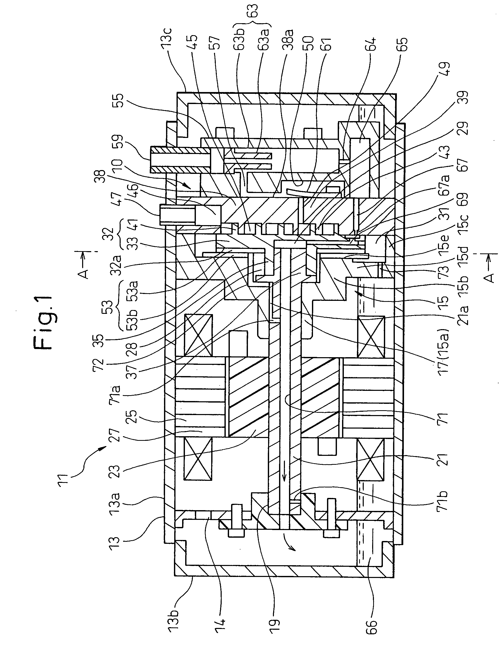
[0116]FIG. 1 is a longitudinal sectional view showing a scroll compressor 11 according to this embodiment. This embodiment represents a compressor for a water heater in the refrigeration circuit which uses carbon dioxide as a refrigerant and in which the pressure of carbon dioxide discharged exceeds the critical pressure thereof. Nevertheless, the invention is not limited to this compressor.

[0117]The scroll compressor 11 according to this embodiment is a motor driven hermetic compressor having a closed container 13 accommodating a motor unit 27 and a compression mechanism 10.

[0118]The closed container 13 includes a cylindrical case 13a, a motor-side end case 13b assembled and a compression mechanism-side end case 13c at each end of the cylindrical case 13a.

[0119]The motor unit 27 includes a stator 25 fixed on the inner peripheral surface of the cylindrical case 13a and a rotor 23 fixed on th...

Example

Second Embodiment

[0172]Although the shaft 21 is arranged in a horizontal direction in the first embodiment described above, the invention is not limited to this configuration, and applicable also to a compressor having the shaft 21 arranged vertically as shown in FIG. 12. In FIG. 12, the component parts identical with those of the first embodiment are designated by the same reference numerals, respectively.

[0173]In FIG. 12, the lubricating oil and the refrigerant flowing in from the intake tube 47 lubricate the auxiliary bearing 19 while at the same time being led to the motor chamber with the motor unit 27 arranged therein inside the closed container 13 through the opening formed in the support member 14. The refrigerant and the oil led to the motor chamber lubricate the main bearing 17 and the crank mechanism 28 on the one hand and the oil is supplied to the thrust bearing 53 through the vertical hole formed in the middle housing 15 and led to the intake chamber 46 on the other ha...

Example

Third Embodiment

[0190]Next, a third embodiment of the invention will be explained. The parts of the compressor not described below in the third embodiment are similar to the corresponding parts, respectively, of the compressor described in the first embodiment above.

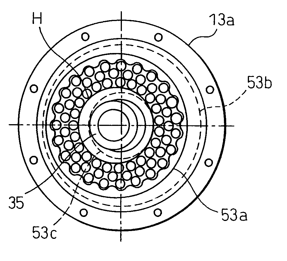
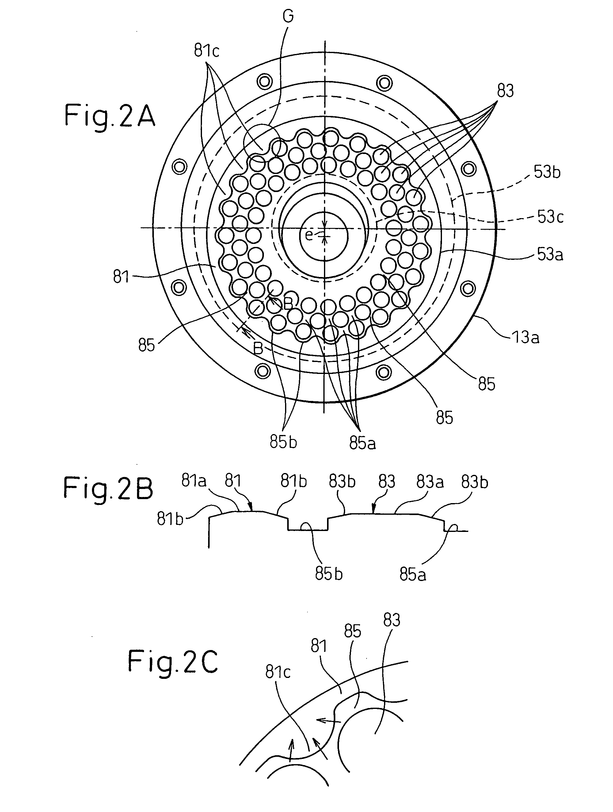
[0191]According to this embodiment, the thrust bearing 53, as shown in FIG. 13, includes a pair of sliding surfaces 100 and 101. The first sliding surface 100 constitutes the surface of a scroll-side plate 53a in opposed relation to the housing-side plate 53b. The second sliding surface 101, on the other hand, constitutes the surface of the housing-side plate 53b in opposed relation to the scroll-side plate 53a.

[0192]As described above, the first sliding surface 100, as shown in FIG. 2A, is formed with a multiplicity of insular pressure receiving portions 83. In the second sliding surface 101, on the other hand, the portion thereof in opposed relation to the first sliding surface 100 is substantially flat, as shown in F...


PUM


Abstract

A scroll compressor is disclosed. A plurality of grooves (85) communicating with each other are formed on a sliding surface of a thrust bearing (53) subjected to the axial force received by a movable scroll (32). The areas surrounded by the plurality of the grooves (85) make up a plurality of insular pressure receiving portions (83) independent of each other. The pressure receiving portions (83) represent at least one half of the area of the sliding surface.

Description

BACKGROUND OF THE INVENTION[0001]1. Technical Field of the Invention[0002]This invention relates to a scroll compressor.[0003]2. Description of the Related Art[0004]Generally, a scroll compressor includes a scroll fixed on a housing and a movable scroll arranged in opposed relation to the fixed scroll and adapted to revolve with respect to the fixed scroll on a rotary shaft, so that a fluid is compressed by the fixed scroll and the movable scroll. The movable scroll is subjected to the force in thrust direction by the pressure difference between the back surface of the movable scroll and the compressed fluid. This force in thrust direction is supported by a thrust bearing.[0005]Since the movable scroll orbits, the sliding speed is lower in the case where the thrust bearing is used with the scroll compressor than in the case where the thrust bearing is used with a rotating device. As a result, it is difficult for the lubricating oil to form an oil film on the sliding surfaces, often ...

Claims


Application Information

Patent Timeline
IPC IPC(8): F01C21/04
CPCF04C18/0215F04C18/0253F04C29/02F05C2251/14F04C2240/54F05C2251/10F04C2230/92
Inventor IWANAMI, SHIGEKIKAWABATA, SANEMASAHOTTA, TADASHIINOUE, TAKASHIKAWANO, SHIGERUKOMURA, MASATOAKIYAMA, YOSHITAKA
Owner NIPPON SOKEN
Why Eureka
Try Eureka