Power transmission chain, method for manufacturing power transmission member of the power transmission chain, and power transmission device

Active Publication Date: 2008-02-28
JTEKT CORP
View PDF11 Cites 8 Cited by
  • Summary
  • Abstract
  • Description
  • Claims
  • Application Information

AI Technical Summary

Benefits of technology

[0009] According to the invention, it is possible to enlarge the surface area of the bulging curved faces sufficiently. The contacting area between the bulging curved faces and the sheave faces of the pulleys can be sufficiently retained to receive the loads from the sheave faces of the pulleys in the bulging curved faces. The sheave faces can be prevented from contacting with the edges (or the edge portions) of the end faces of the power transmission members thereby to prevent the edge abutment so that the advance of the wear of the end faces of the power transmission members can be drastically reduced.
[0013] In this case, the meshing periods for the individual power transmission members to be sequentially meshed with the pulleys are made random so that the frequency of these meshing noises can be distributed over a wide range thereby to reduce the peak value. As a result, it is possible to drastically reduce the noises accompanying the drive of the power transmission chain. Moreover, even the end faces of the first members thinned can contact with the sheave faces of the pulleys in the bulging curved faces thereby to prevent the edge abutments against the sheave faces.
[0014] According to the invention, there is provided a method for manufacturing a power transmission members (3) for said power transmission chain (1), comprising: rotating a grinding wheel (34) having a pair of grinding faces (39) for grinding a pair of end faces (33) of a manufacture intermediate (31) of a rod-shaped power transmission member simultaneously; rotating a carrier (32) for holding said manufacture intermediate (31) in parallel with the axis of rotation (34a) of said grinding wheel (34), on the axis of rotation (32a) parallel to the axis of rotation (34a) of the grinding wheel (34); and passing the paired end faces (33) of the manufacture intermediate (31) between said paired grinding faces (39). In this case, by the simple method for passing the manufacture intermediate of the power transmission members through the paired grinding faces, the bulging curved faces can be simultaneously formed on the end faces of the power transmission members thereto to reduce the dispersion of the whole lengths of the power transmission members.
[0015] According to the invention, there is provided a power transmission device comprising: first and second pulleys (60 and 70) including a pair of sheave faces (62a and 63a, and 72a and 73a) of a conical shape confronting each other; and said power transmission chain (1) made to run between those pulleys (60 and 70) for transmitting the power in engagement with the sheave faces (62a and 63a, and 72a and 73a). In this case, it is possible to realize the power transmission device, which is excellent in durability while suppressing the wears of the power transmission members and the wears of the sheave faces.

Problems solved by technology

As a result, when the end faces contacts with the taper disk, only the portion on the inner side of the edge (or edge portion) of the end face cannot retain a sufficient contact area thereby to cause a possible edge abutment, in which even the edge contacts with the taper disk.
When the edge abutment occurs, the wear of the end face is undesirably promoted locally.

Method used


Image

  • Power transmission chain, method for manufacturing power transmission member of the power transmission chain, and power transmission device
  • Power transmission chain, method for manufacturing power transmission member of the power transmission chain, and power transmission device
  • Power transmission chain, method for manufacturing power transmission member of the power transmission chain, and power transmission device

Examples


Embodiment Construction

[0023] Preferred modes of embodiment of the invention are described with reference to the accompanying drawings.

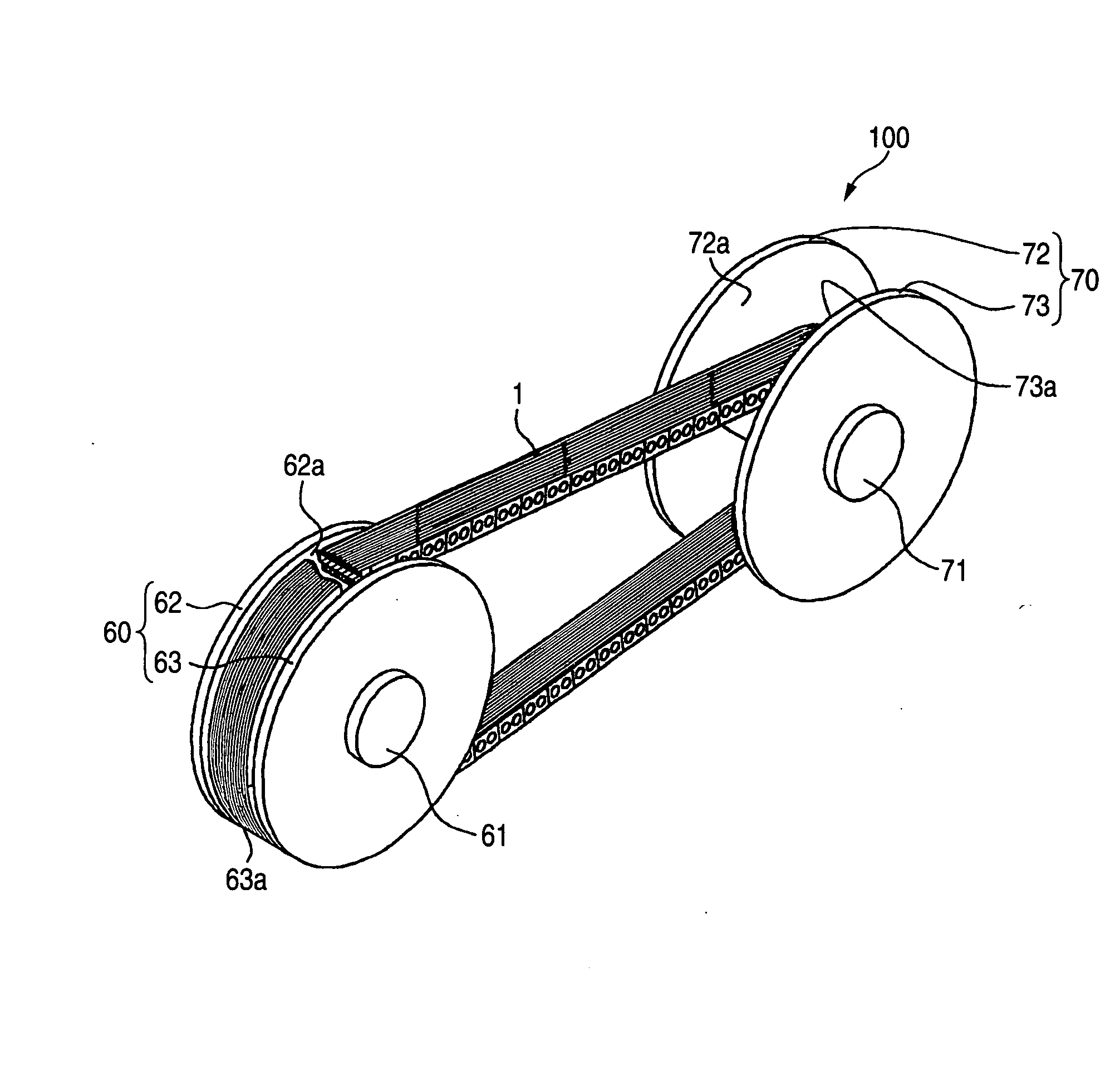
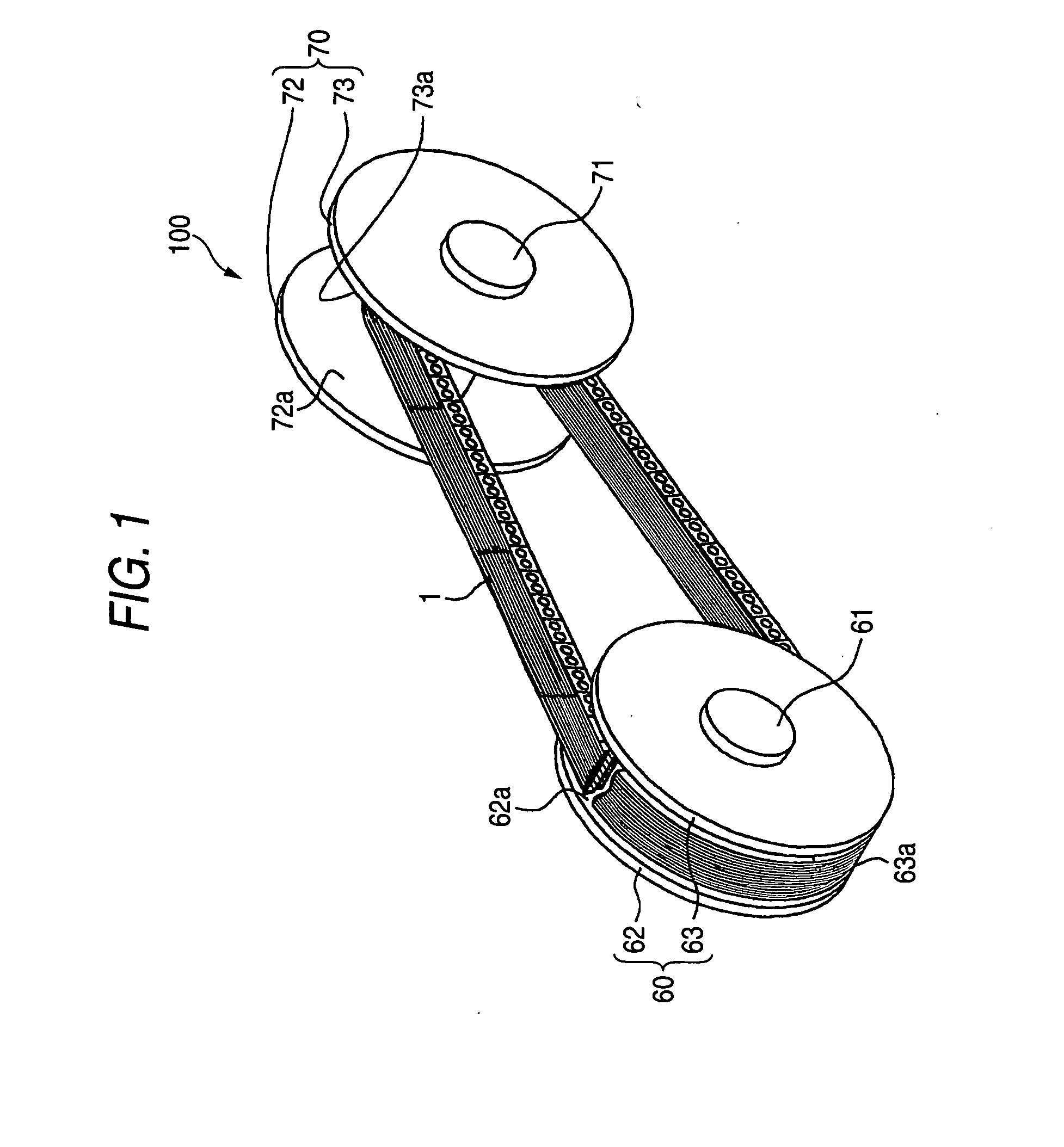
[0024]FIG. 1 is a perspective view schematically showing an essential constitution of a chain type continuously variable transmission (as will also be merely called the “continuously variable transmission”) as a power transmission device, which is equipped with a power transmission chain according to one mode of embodiment of the invention. With reference to FIG. 1, a continuously variable transmission 100 is mounted on a vehicle such as an automobile, and is constituted to include: a first pulley or a drive pulley 60 made of a metal (e.g., structural steel); a second pulley or a driven pulley 70 made of a metal (e.g., structural steel); and an endless power transmission chain 1 (as will be merely called the “chain”) wound between those two pulleys 60 and 70. Here, the chain 1 in FIG. 1 is shown so partially sectionally as can be easily understood.

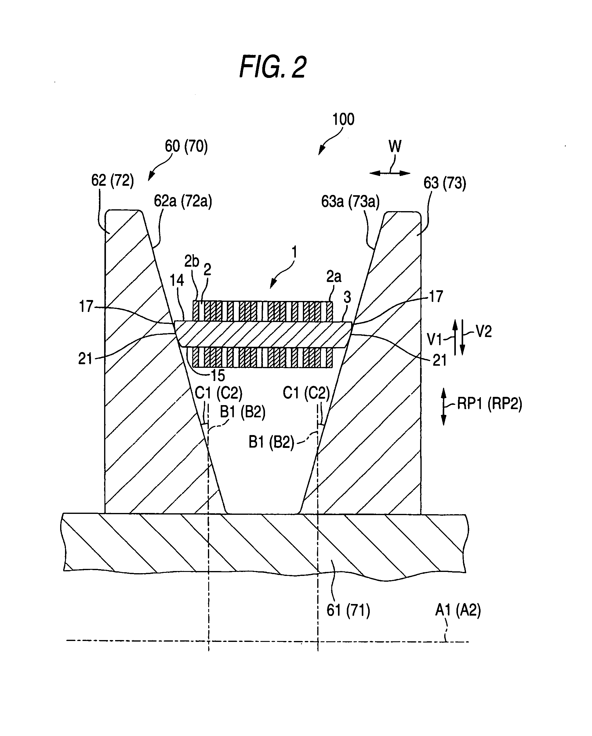
[0025]FIG. 2 is a parti...


PUM

PropertyMeasurementUnit
Poweraaaaaaaaaa
Shapeaaaaaaaaaa
Radiusaaaaaaaaaa

Abstract

The end faces of a first pin contain bulging curved faces having an egg-like shape, when viewed along a chain width direction. Each bulging curved face includes a first end portion, a second end portion and a maximum width portion with respect to a chain advancing direction. With respect to perpendicular directions, the distance between the center of the maximum width portion and the first end portion is relatively large, whereas the distance between the center of the maximum width portion and the second end portion is relatively short. It is possible to enlarge the surface area of the bulging curved face.

Description

BACKGROUND OF THE INVENTION [0001] 1. Field of the Invention [0002] The present invention relates to a power transmission chain, a method for manufacturing a power transmission member of the power transmission chain, and a power transmission device. [0003] 2. Related Art [0004] In an endless power transmission chain to be used in a power transmission device such as a pulley type continuously variable transmission (CVT) of an automobile, links adjoining in a chain advancing direction are connected by pins and inter-pieces (as referred to Pamphlet of International Publication No. WO 2005 / 045280 A1, for example). The paired end faces of the pins engage with the corresponding taper disks of the pulleys thereby to transmit the power. [0005] The end face of the pin is tapered the more as the pin advances from the intermediate portion of the chain radial direction to the end portion on the outer side, so that the outer side end portion has a smaller area. As a result, when the end faces co...

Claims


Application Information

Patent Timeline
IPC IPC(8): F16H55/52B21L11/00F16G13/02
CPCF16H9/18F16G5/18
Inventor TADA, SEIJIKAMAMOTO, SHIGEO
Owner JTEKT CORP
Why Eureka
Try Eureka