
Eureka
For R&D, Eureka makes reading and utilizing patents & technical documents easy.
Eureka AIR
Designed for self-driven R&D workflows. Generate viable solutions, solve complex R&D challenges, empower your innovation with AI.

Eureka Materials
Designed for material experts only. Revolutionize your material R&D, from search, analyze, to developing new materials.

TechResearch
Generate reliable direction feasibility study reports for your R&D in just a few steps.

TechSeek
Discover and master advanced knowledge NOW. Basics, ideas, possibilities, all at once.

TechMind
As an expert in R&D Theories, TechMind can generates customized viable solutions instantly.

TechRisk
Analyze your overall solution with one click, know your potential R&D risks in advance.

TechMonitor
Get weekly tech updates, stay abreast of the latest tech innovations and key insights.
Processes for separation of fluoroolefins from hydrogen fluoride by azeotropic distillation
- Summary
- Abstract
- Description
- Claims
- Application Information
AI Technical Summary
Problems solved by technology
Method used
Image

Examples
example 1
Dehydrofluorination of HFC-236ea to HFC-1225ye (E and Z Isomers) Over Carbonaceous Catalyst
[0214]To a Hastelloy nickel alloy reactor (1.0″ OD×0.854″ ID×9.5″ L) was charged 14.32 g (25 mL) of spherical (8 mesh) three dimensional matrix porous carbonaceous material prepared substantially as described in U.S. Pat. No. 4,978,649. The packed portion of the reactor was heated by a 5″×1″ ceramic band heater clamped to the outside of the reactor. A thermocouple, positioned between the reactor wall and the heater measured the reactor temperature. After charging the reactor with the carbonaceous material, nitrogen (10 mL / min) was passed through the reactor and the temperature was raised to 200° C. during a period of one hour and maintained at this temperature for an additional 4 hours. The reactor temperature was then raised to the desired operating temperature and a flow of HFC-236ea and nitrogen was started through the reactor.
[0215]A portion of the total reactor effluent was sampled on-lin...
example 2
Azeotropic Distillation for the Separation of HFC-1225Ve from HF without an Entrainer
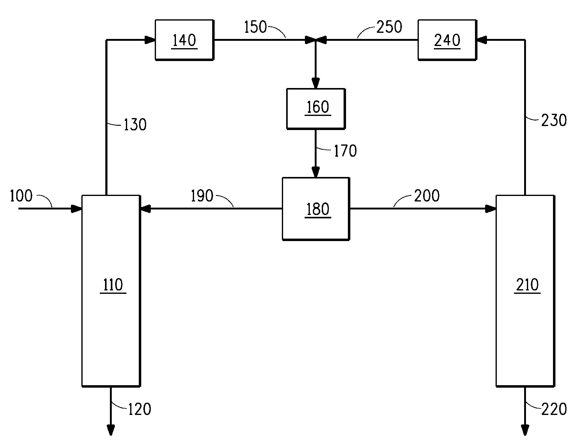
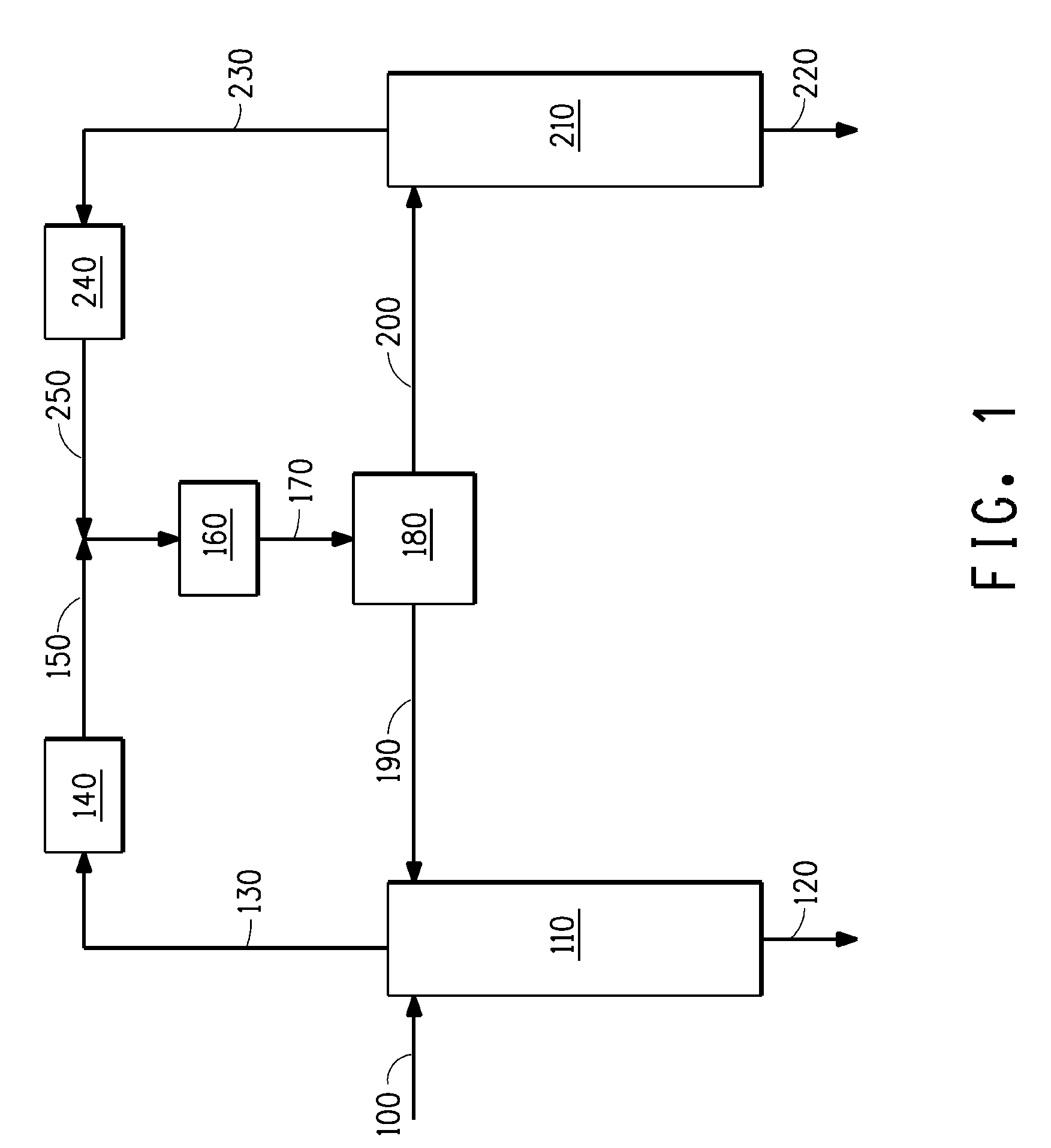
[0217]Example 2 demonstrates that HF may be separated from HFC-1225ye by azeotropic distillation with no entrainer. Referring now to FIG. 1, a composition comprising HF and HFC-1225ye is fed to a first column 110 via stream 100. This first column contains 8 theoretical stages and is operated under appropriate conditions to approach the low-boiling HF / HFC-1225ye azeotrope. Because HF is being fed to this first column in excess of that needed to form the azeotrope with the HFC-1225ye, HF is recovered as a product stream out the bottoms of the column via stream 120, while a composition near to the HF / HFC-1225ye azeotrope is recovered as distillate via stream 130. Stream 130 is condensed in 140, mixed with the nearly azeotropic composition recycled from the second column via stream 250 and the combined stream is sub-cooled in cooler 160 and sent to decanter 180 where the combined stream 170 separates in...
example 3
Azeotropic Distillation for the Separation of HFC-1225ve from HF Using Propane as the Entrainer
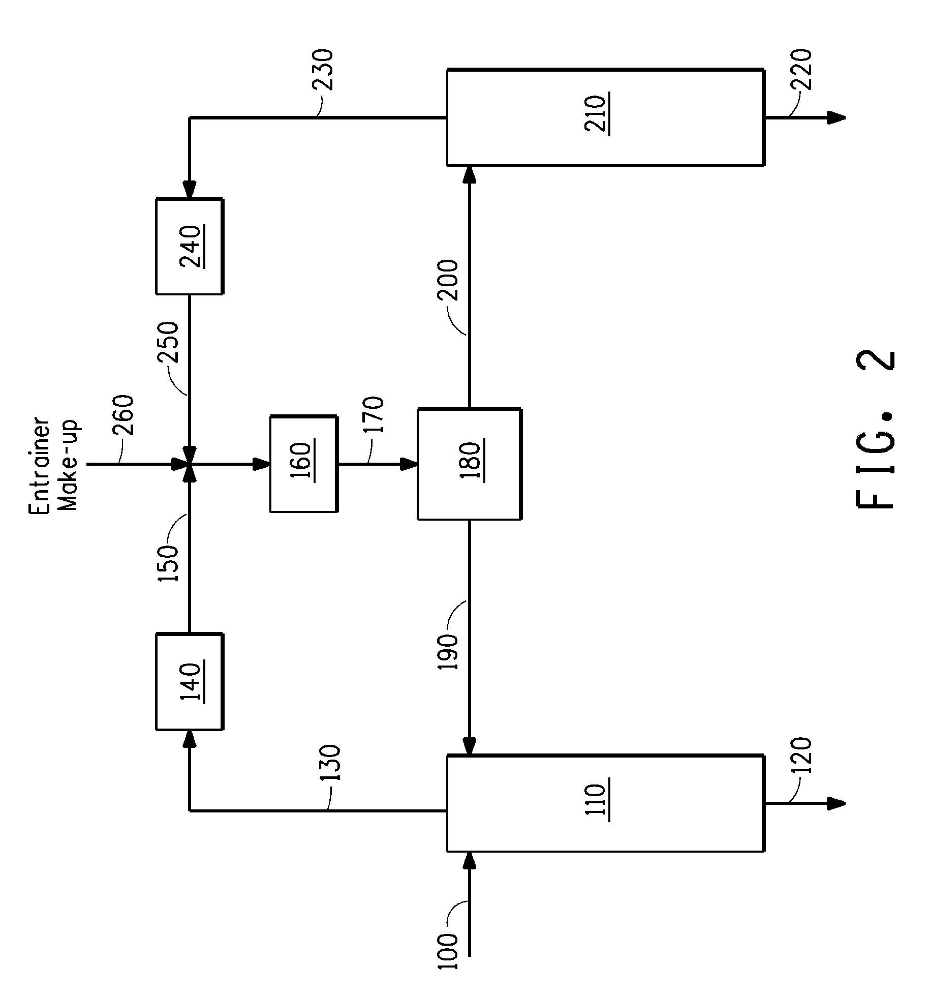
[0219]Example 3 demonstrates that HF may be separated from HFC-1225ye by azeotropic distillation using propane as the entrainer. This ternary mixture forms three minimum-boiling binary azeotropes and a minimum-boiling ternary azeotrope.
[0220]Referring now to FIG. 2, a composition consisting of HF and HFC-1225ye is fed to a first column 110 containing 8 theoretical stages via stream 100. An HF-rich and propane-lean composition is also fed to the top stage of column 110 via stream 190. Because the combined amount of HF in streams 100 and 190 is in excess of that needed to form the low-boiling HF / HFC-1225ye azeotrope, HF is recovered as a product stream essentially free of both HFC-1225ye and propane from the bottom of column 110 via stream 120. A composition near the HF / HFC-1225ye azeotrope is recovered as the distillate via stream 130. Stream 130 is condensed by condenser 140 forming stream...
PUM
| Property | Measurement | Unit |
|---|---|---|
| Temperature | aaaaa | aaaaa |
| Temperature | aaaaa | aaaaa |
| Temperature | aaaaa | aaaaa |
Abstract
Description
Claims
Application Information
 - R&D Engineer
- R&D Manager
- IP Professional
- Industry Leading Data Capabilities
- Powerful AI technology
- Patent DNA Extraction
Browse by: Latest US Patents, China's latest patents, Technical Efficacy Thesaurus, Application Domain, Technology Topic, Popular Technical Reports.
© 2024 PatSnap. All rights reserved.Legal|Privacy policy|Modern Slavery Act Transparency Statement|Sitemap|About US| Contact US: help@patsnap.com