Method of controlling the path of a vehicle

Active Publication Date: 2008-02-28
ROBERT BOSCH GMBH
View PDF3 Cites 3 Cited by
  • Summary
  • Abstract
  • Description
  • Claims
  • Application Information

AI Technical Summary

Benefits of technology

[0011]This better estimate of the vehicle load, combined with the estimate of the gradient, allows systems of the ABS, E

Problems solved by technology

However, the load estimate is dependent on the estimate of the gradient of the roadway on which the vehicle is running and this gradient estimate is currently somewhat i

Method used


Image

  • Method of controlling the path of a vehicle
  • Method of controlling the path of a vehicle
  • Method of controlling the path of a vehicle

Examples


Embodiment Construction

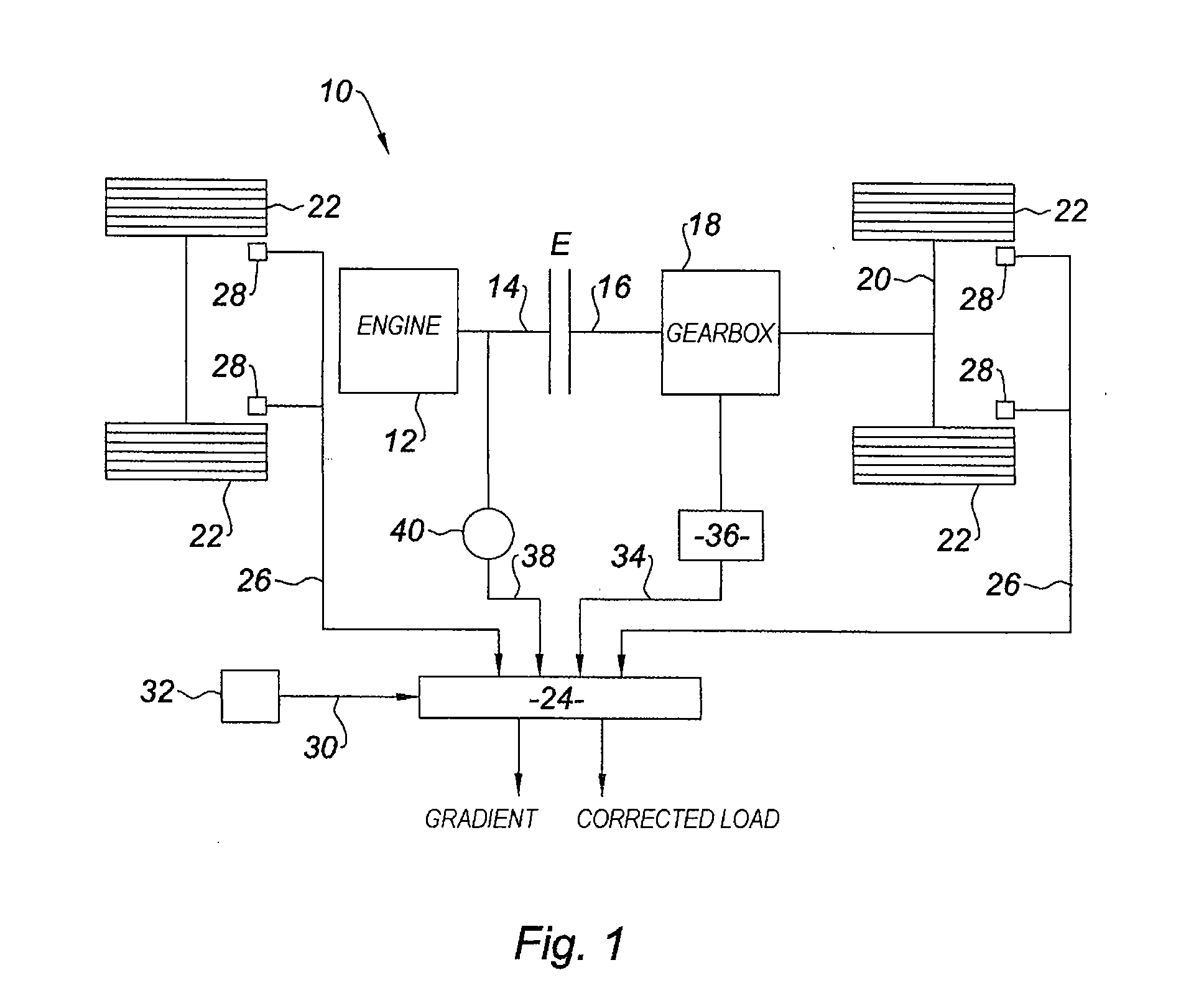
[0023]In FIG. 1, the reference 10 denotes, in general, a motor vehicle, of which the internal combustion engine 12 via a clutch E connecting its output shaft 14 to the input shaft 16 of a gearbox 18 and a drive line 20, drives the wheels 22 of the vehicle.

[0024]The means for determining the gradient according to the invention comprise data processing means 24 which receive at input a signal 26 representative of the speed of the vehicle and supplied by a sensor 28 that senses the rotational speed of the wheels 22, a signal 34 that the clutch has been let out, this signal being supplied by gearshift means 36 (which may be controlled by the driver of the vehicle or may be automated in the case of an automatic gearbox) and / or a signal 38 representative of the rotational speed of the engine output shaft and supplied by an appropriate sensor 40.

[0025]Advantageously, the ESP computer, also associated with a hydraulic unit equipped, in the known way, with a hydraulic pump and with valves co...


PUM


Abstract

Method for determining the gradient on which a motor vehicle is traveling, comprising a step (44) of detecting disengagement of the clutch, a step (46) of measuring the variation in speed of the vehicle on the gradient when the clutch is disengaged, a step (48) of estimating the vehicle load, and a comparison (50) with calibration curves stored in memory and providing deceleration values for various gradients and various vehicle loads at various vehicle speeds.

Description

BACKGROUND OF THE INVENTION[0001]The invention relates to a method for determining the gradient of a roadway on which a motor vehicle is traveling, and for determining the mass of the vehicle and to a device for controlling the path of the vehicle using the mass value thus determined.SUMMARY OF THE INVENTION[0002]Present-day motor vehicles are equipped with driving aid systems, particularly with anti-lock braking systems (ABS), electronic stability programs (ESP) for controlling the path of the vehicle, and / or with traction control systems (TC) for preventing the driven wheels from spinning, and these systems are capable, according to the circumstances, of modifying the braking force applied to each wheel of the vehicle or of generating a braking force.[0003]The systems for controlling the path are particularly designed to estimate, in real time, and while the vehicle is running, the load of the vehicle, that is to say its total weight, so as to be able to take the estimated load in...

Claims


Application Information

Patent Timeline
IPC IPC(8): B60T7/12G05D13/00B60W10/18B60W30/18B60W40/06B60W40/12
CPCB60G2400/106G01G19/086B60G2800/019B60G2800/0192B60G2800/702B60G2800/922B60T8/172B60T2250/02B60W10/02B60W10/184B60W30/18172B60W40/072B60W40/076B60W40/13B60W2520/105B60W2550/142B60W2710/18F16H59/66B60G2400/824B60W2552/15
Inventor BOUCHARD, CHRISTOPHE
Owner ROBERT BOSCH GMBH
Why Eureka
Try Eureka