
System and Method to Optimize Multi-Core Microprocessor Performance Using Voltage Offsets

Inactive Publication Date: 2008-02-28
IBM CORP
View PDF23 Cites 15 Cited by
  • Summary
  • Abstract
  • Description
  • Claims
  • Application Information

AI Technical Summary

Benefits of technology

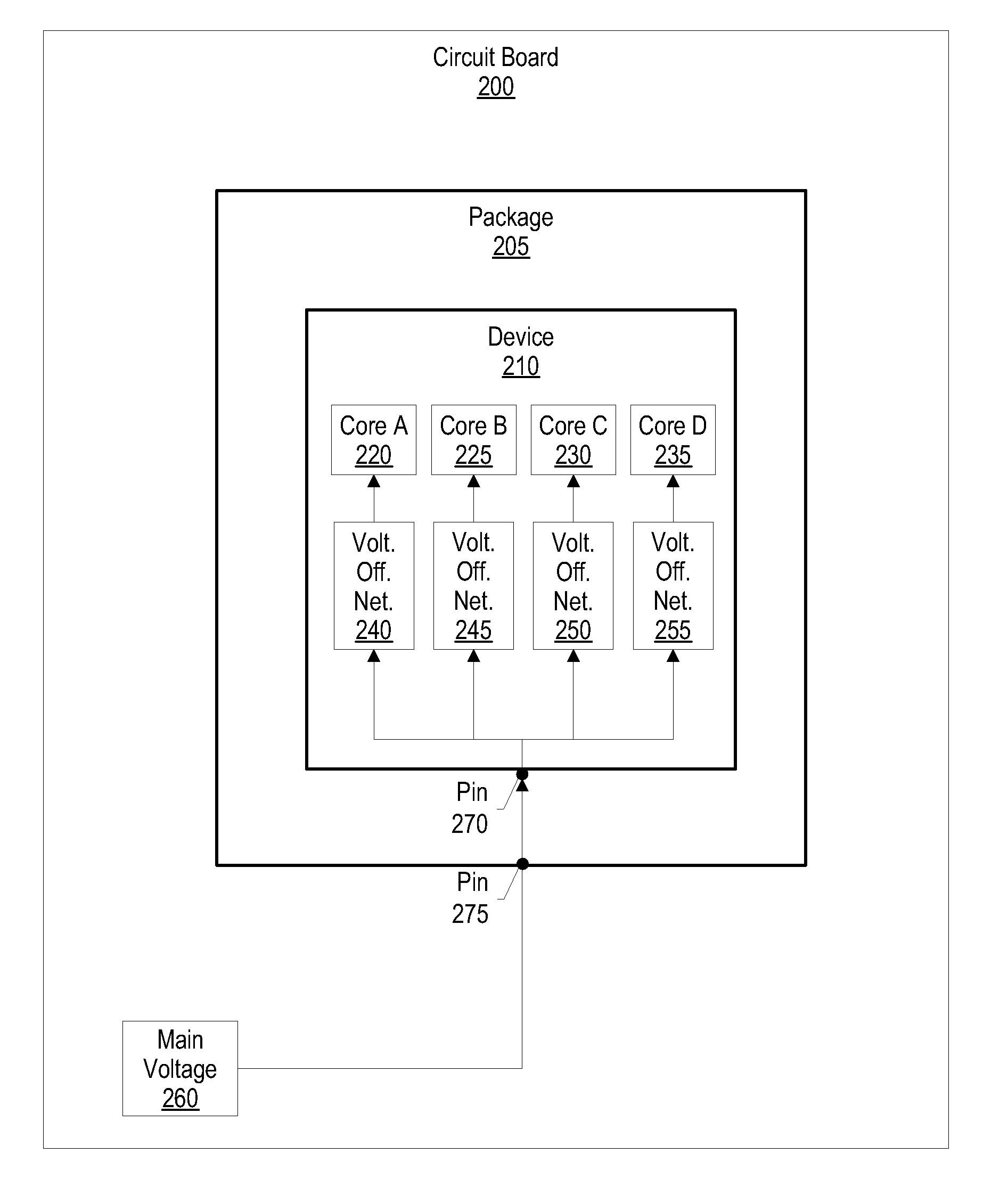
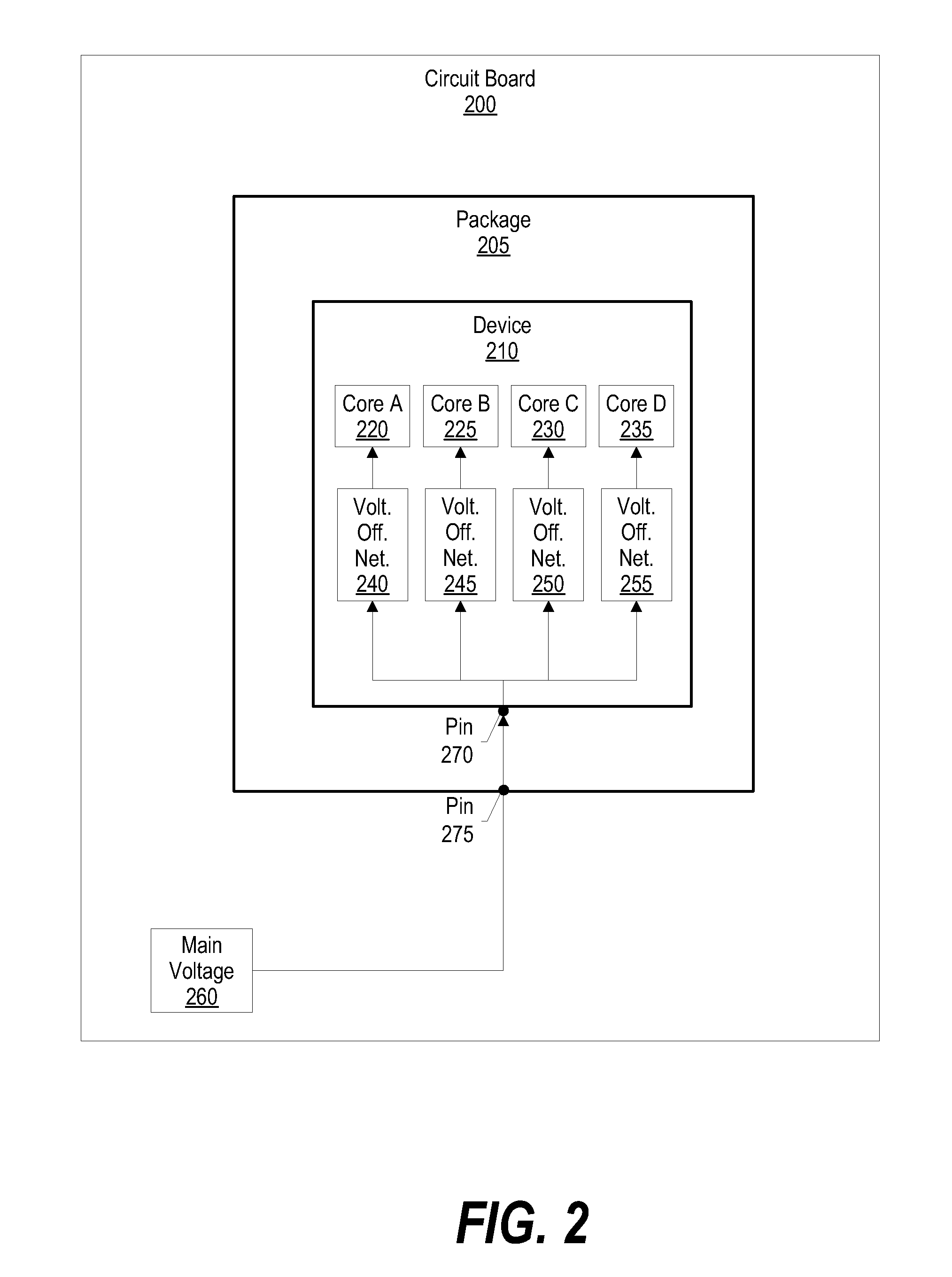
[0014]In another embodiment, a device configures a control circuit to dynamically generate a voltage offset value based upon particular device parameters, such as the device's temperature or performance requirements. In this embodiment, the voltage offset network may also include various resistors and / or transistors to produce particular voltage offsets and / or to support large current requirements. Since specific processor core voltages are generated within the multi-core device, the device requires a single supply voltage that, as a result, reduces package and circuit board cost and complexity.

Problems solved by technology

A challenge found is that each processor core may require a specific supply voltage due to different core types and process variations.
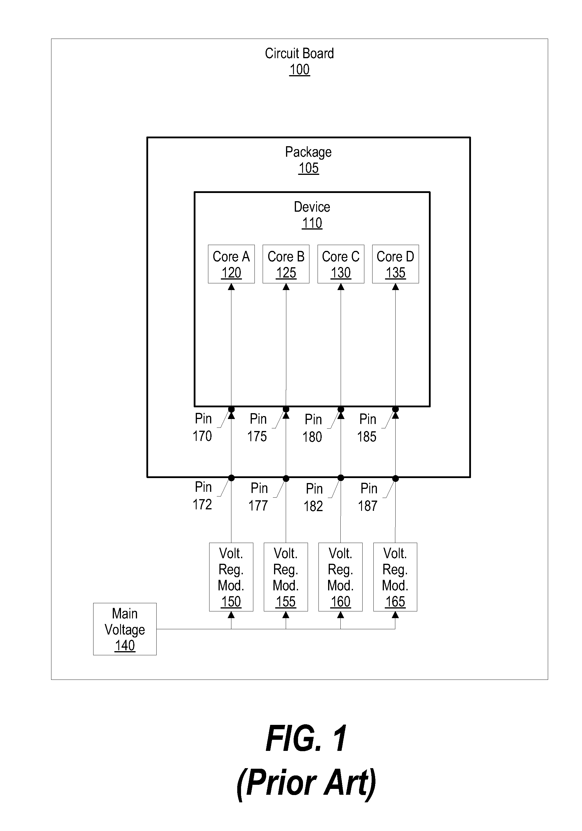
A challenge found with this approach, however, is that each voltage plane is connected to different pins on the device for receiving different external supply voltages, thus reducing the amount of pins that the device has available for other functions.
A challenge found with this approach is that using multiple voltage regulator modules increases production cost as well as board layout complexity.
In addition, the extra power planes in the package also increase package cost and complexity.
While this approach may minimize cost and simplify board layout, the result is a device that does not operate at its optimum performance level.
Since specific processor core voltages are generated within the multi-core device, the device requires a single supply voltage that, as a result, reduces package and circuit board cost and complexity.

Method used


Image

  • System and Method to Optimize Multi-Core Microprocessor Performance Using Voltage Offsets
  • System and Method to Optimize Multi-Core Microprocessor Performance Using Voltage Offsets
  • System and Method to Optimize Multi-Core Microprocessor Performance Using Voltage Offsets

Examples


Embodiment Construction

[0029]The following is intended to provide a detailed description of an example of the invention and should not be taken to be limiting of the invention itself. Rather, any number of variations may fall within the scope of the invention, which is defined in the claims following the description.

[0030]FIG. 1 is a diagram showing a prior art implementation of providing specific supply voltages to each processor core within a multi-core device. Circuit board 100 includes package 105 (e.g., ball grid array package). Package 105 includes multi-core device 110, which comprises core A 120, core B 125, core C 130, and core D 135. In order to perform at an optimum level, each of these cores requires a specific supply voltage due to process variations and different core types. For example, core A 120, core B 125, core C 130, and core D 135, may require supply voltages of 1.73V, 1.84V, 1.54V, and 1.95V, respectively, to achieve optimum performance.

[0031]In order to provide specific supply volta...


PUM


Abstract

A system and method to optimize multi-core microprocessor performance using voltage offsets is presented. A multi-core device tests each of its processor cores in order to identify each processor core's optimum supply voltage. In turn, the device configures voltage offset networks for each processor core based upon each processor core's identified optimum supply voltage. As a result, the offset voltages produced by the voltage offset networks are subtracted from the multi-core device's main voltage, which results in the voltage offset networks supplying optimum supply voltages to each processor core. The voltage offset networks may include fuses to generate a fixed voltage offset, or the voltage offset networks may include a control circuit to dynamically adjust voltage offsets during the multi-core device's operation.

Description

BACKGROUND OF THE INVENTION[0001]1. Technical Field[0002]The present invention relates to a system and method to optimize multi-core microprocessor performance using voltage offsets. More particularly, the present invention relates to a system and method to internally generate processor core optimum supply voltages within a device by using voltage offset networks to produce specific offset values for each processor core.[0003]2. Description of the Related Art[0004]Processing devices today include multiple “cores” in order to achieve a higher performance level. These cores may work together, or individually, to execute particular functions within an application. For example, a multi-core processing device may include multiple digital signal processor cores in order to effectively execute highly computational tasks, such as with a gaming application.[0005]One aspect of a processor core's performance is based upon its supply voltage. A processor core's “optimum” supply voltage is a vol...

Claims


Application Information

Patent Timeline
IPC IPC(8): G06F1/00
CPCG06F1/26G06F1/32
Inventor CAPPS, LOUIS BENNIEDYCKMAN, WARREN D.FERRIS, JOANNEHARIDASS, ANANDJORDAN, JAMES DOUGLASNEWHART, RONALD EDWARDOUELLETTE, MICHAEL RICHARDSHAPIRO, MICHAEL JAY
Owner IBM CORP
Learn More