Devices, methods and systems for fuel monitoring

a fuel monitoring and device technology, applied in the direction of optical radiation measurement, instruments, spectrometry/spectrophotometry/monochromators, etc., can solve the problems of two phasing, system instability, and failure of floating system

Inactive Publication Date: 2008-03-06
PLAIN SIGHT SYST
View PDF9 Cites 47 Cited by
  • Summary
  • Abstract
  • Description
  • Claims
  • Application Information

AI Technical Summary

Benefits of technology

[0009] It is an object of the present invention to measure the composition of fuels as a function of the height within a fuel storage tank. In some embodiments of the present invention, as detailed herein, this is accomplished by measuring optical or dielectric spectral features of the fuel by a series of sensors placed at a series of heights within the storage tank. In some embodiments, individual sensors disposed vertically, that happen to sit at an interface between different phases / layers within the fuel storage tank, can be used to determine the level of the interface more precisely. This is accomplished, in part, by using the spectral properties of the fuel to determine the fraction F of phase 1 vs. phase 2 within the vertical sensor. Combined optionally with other information including but not limited to density data of the different phases, this information is used to determine the height of the interface as it is in direct proportion to the fraction F.

Problems solved by technology

These systems are inherently unstable and in the presence or upon the introduction of water will separate into a two-layer formation where the lower layer is comprised of the water and ethanol in the system and the upper layer is comprised primarily of the fuel such as gasoline, iso-octane fuel, etc.
This creates a particular problem when fuel is to be transferred from a first container to a second container.
In prior art systems, typically employing floats, gasoline and water layer separation can be measured, but the added complexity introduced by ethanol in the system causes such float based systems to fail, in part because the density of water-ethanol mixes is not the same as the density of water alone.
When this happens, the addition of more fuel can stir up the mixture, thus introducing the water into the fuel and causing two phasing.

Method used


Image

  • Devices, methods and systems for fuel monitoring
  • Devices, methods and systems for fuel monitoring
  • Devices, methods and systems for fuel monitoring

Examples


Embodiment Construction

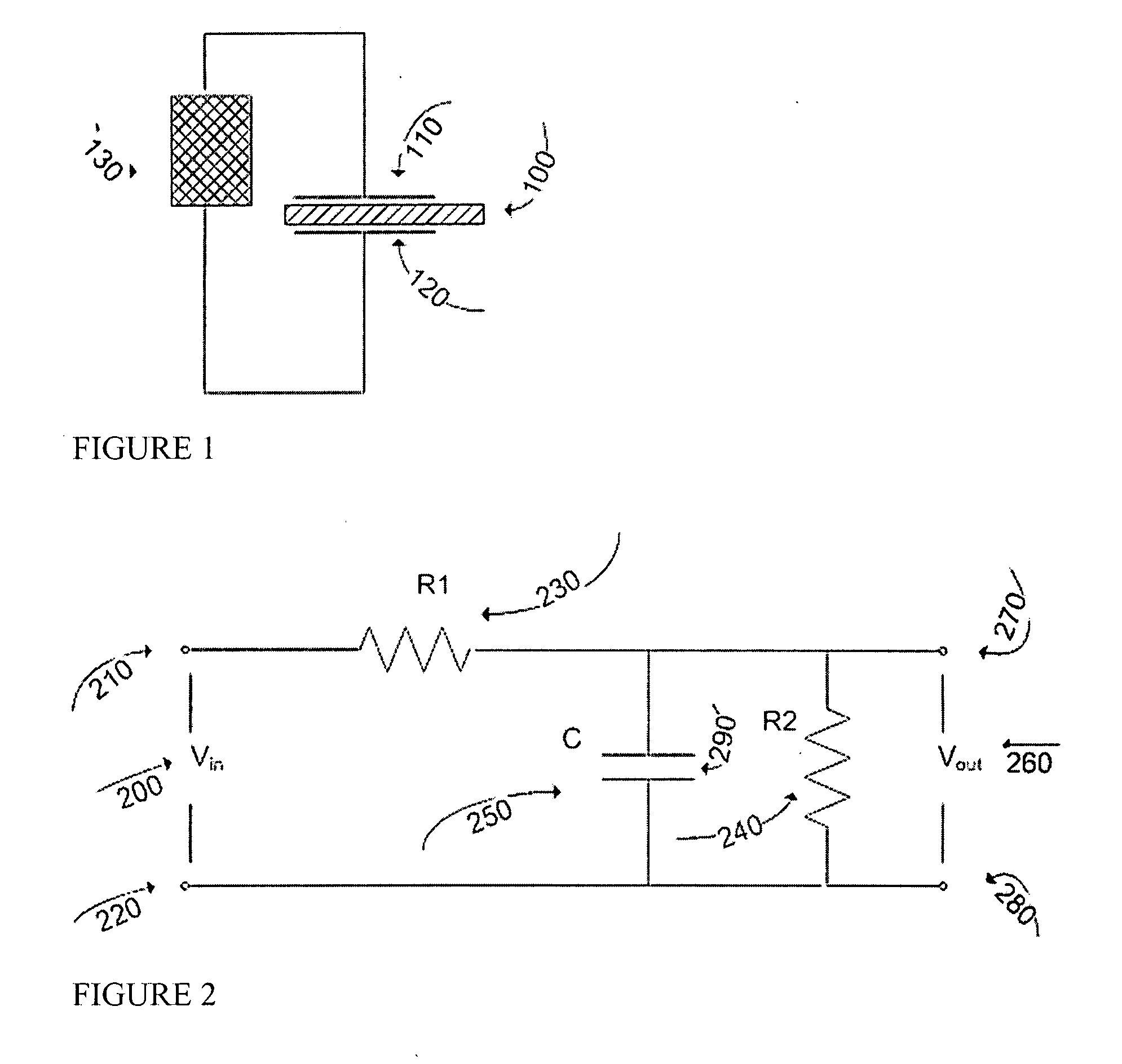
[0019] Turning now to FIG. 1, when a material (100) such as but not limited to a fuel mixture, substantially occupies the space between two plates (110) and (120), then a circuit (130) disposed to measure the capacitance between the two plates will measure an amount that depends on the dielectric constant of the material (100). Note that material (100) is meant to illustrate the presence of a material or substance (100) between the plates (110) and (120). While the combination (100), (110) and (120) in the figure resembles in some ways the electronic schematic symbol for a crystal, this is not the intended meaning of these symbols in FIG. 1.

[0020]FIG. 2 shows a schematic of a capacitance measuring circuit. An input signal Vin (200) is applied across input terminals (210) and (220). A circuit is comprised of resistors R1 (230), and R2 (240) and capacitor C (250), such capacitor including but not limited to a capacitive sensor as disclosed herein. An output signal Vout (260) across o...


PUM

PropertyMeasurementUnit
dielectric constantaaaaaaaaaa

Abstract

Disclosed are devices, methods and systems for the measurement of fuel composition and the detection and measurement of phase separation in fuel storage tanks. An embodiment measures optical and/or electrical impedance spectral features of the fuel by a series of sensors placed at a series of heights within a fuel storage tank. Embodiments are disclosed to measure aspects of the water, ethanol and gasoline content as well as other constituents of a fuel mixture, as well as the onset of the two phase event and the completed extent of the water intrusion into the system in concert with the level at which the layers exist in a fuel container.

Description

RELATED APPLICATION [0001] This application claims priority benefit under Title 35 U.S.C. §119(e) of provisional patent application No. 60 / 791,764 filed Apr. 13, 2006, which is incorporated by reference in its entirety.BACKGROUND AND FIELD OF THE INVENTION [0002] The present invention relates generally to devices, methods and systems for measurement and monitoring of the chemical and physical properties of fuels in storage containers, fuel tanks, fuel lines and pipelines, and more specifically, in part, to the detection and measurement of “two phasing” in petrochemicals in storage containers and fuel tanks. Modern petrochemical fuels are often mixed with so called bio-fuels such as ethanol. These bio-fuels are sold in various percentages-by-volume mixes. These systems are inherently unstable and in the presence or upon the introduction of water will separate into a two-layer formation where the lower layer is comprised of the water and ethanol in the system and the upper layer is co...

Claims


Application Information

Patent Timeline
Patent Type & Authority Applications(United States)
IPC IPC(8): G01N33/22G01F23/284G01J3/28
CPCG01N33/2852G01F23/265
Inventor ROHKLIN, VLADIMIRDEVERSE, RICHARD A.MALAN, VANTROY, PAULCOPPI, ANDREAS C.COIFMAN, RONALD R.GESHWIND, FRANKKEARNS, EDFATELEY, WILLIAM G.
Owner PLAIN SIGHT SYST
Why Eureka
Try Eureka