Eureka AIR delivers breakthrough ideas for toughest innovation challenges, trusted by R&D personnel around the world.

Pressure regulation device, in particular for an oxygen emergency supply system in an aircraft

a technology of pressure regulation device and oxygen emergency supply system, which is applied in the direction of fluid pressure control, flying suits, instruments, etc., can solve the problems of no longer being able to close the valve, and achieve the effects of simple and inexpensive design, simple testing of the operability, and good reliability

Inactive Publication Date: 2008-03-06
DAE SYST
View PDF10 Cites 23 Cited by
  • Summary
  • Abstract
  • Description
  • Claims
  • Application Information

AI Technical Summary

Benefits of technology

[0004] Against this background, it is an object of the invention to provide a pressure regulation device of the known type, which with a simple and inexpensive design, has good reliability and ensures a simple testing of its operability.
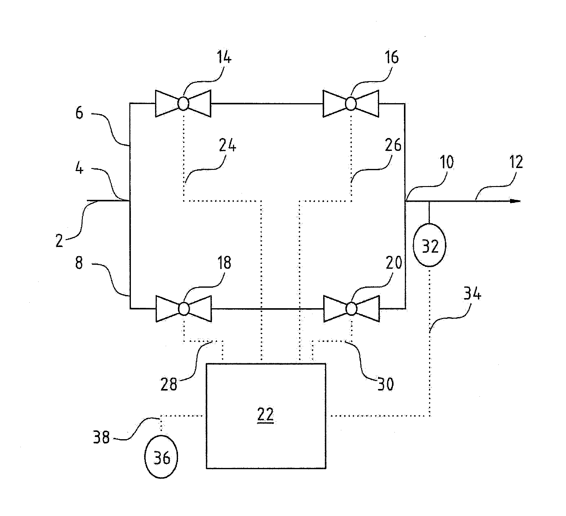
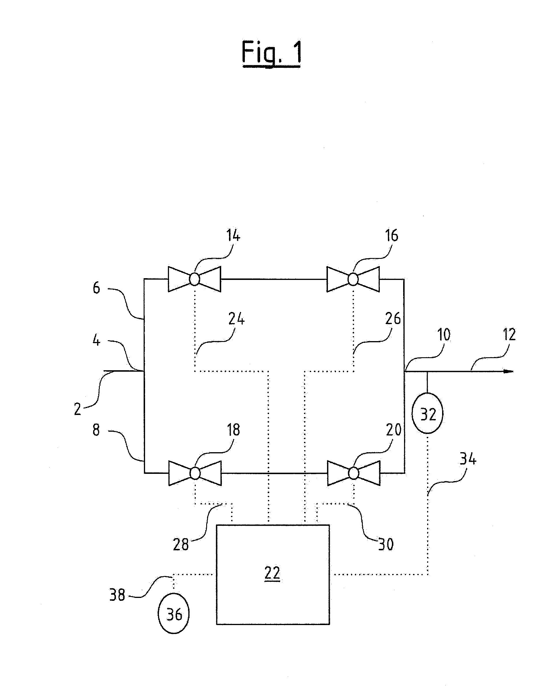
[0007] Apart from this redundancy with regard to possible flow paths, the invention however also provides for an advantageous redundancy with regard to the closeability of these flow paths. Thus, the at least two valves which are arranged behind one another in series in each of the conduits or flow paths, also permit a shut-off of these conduits when one of the valves is blocked in its open position, and a closure of this valve is no longer possible. Thus, the pressure regulation device according to the invention not only provides a greater reliability with regard to the regulation (closed-loop control) behavior, i.e., to the attainment of a predefined pressure desired value, but also reduces the risk of an undesired outflow of the pressure medium.
[0013] In the pressure regulation device according to the invention, the valves may be designed as shut-off valves or as throttle valves. Thus, one advantageous design of the pressure regulation envisages at least one valve being designed as a shut-off valve. The shut-off valve in a first position permits a flow path through the valve, and in a second position permits the complete blockage of this flow path. Accordingly, the shut-off valve or shut-off valves are designed as 2 / 2-way valves, with which a first valve position represents a blocking position, and the second position a through-flow position. The shut-off valve is preferably designed as a seat valve. This design permits a particularly good sealing of the flow path running through the valve, and accordingly has good operational reliability with regard to undesired escape of the gas. Optionally, the shut-off valve may, however, also be designed as a sliding valve.
[0014] In a further advantageous embodiment of the pressure regulation device, at least one valve is designed as a throttle valve. Here, the cross section of the flow path through the throttle valve may be continuously adjusted from a position closing the flow path to a position releasing the flow cross section. In this manner, the throttle valve permits a finer regulation of the exit pressure of the pressure regulation device.
[0016] With the use of throttle valves it is particularly advantageous for the valves to comprise position sensors. This design permits a greater variety of regulation concepts, since in this manner one may set certain throttle cross sections at the valves. This setting of the throttle cross sections also permits a further advantageous design of the pressure regulation device according to the invention, wherein stepper motors are provided for actuating the valves.
[0017] Another favorable design of the pressure regulation device according to the invention envisages a pressure sensor arranged on the entry side of the valve arrangement, which is signal-connected to the controller. Particularly in combinations of valves provided with a position sensor or actuated by stepper motors, this design in combination with suitably designed electronics of the controller permits an evaluation of the quantity or the volume of the compressed gas to be relieved.

Problems solved by technology

Thus, the at least two valves which are arranged behind one another in series in each of the conduits or flow paths, also permit a shut-off of these conduits when one of the valves is blocked in its open position, and a closure of this valve is no longer possible.

Method used


Image

  • Pressure regulation device, in particular for an oxygen emergency supply system in an aircraft
  • Pressure regulation device, in particular for an oxygen emergency supply system in an aircraft

Examples


Embodiment Construction

[0021] The pressure regulation device for the embodiment shown in FIG. 1 is arranged in the oxygen emergency supply system of an aircraft, which is otherwise not shown, in a medium pressure region in the conduit connection between an oxygen storage tank and the oxygen masks of passengers and crew. The pressure regulation device in this embodiment is envisaged for relieving the oxygen pressure of about 10 bar prevailing in this medium pressure region to the required mask pressure.

[0022] The oxygen is supplied to the pressure regulation device via an entry conduit 2 arranged on the entry side. A conduit branching 4, from which two conduits 6 and 8 branch, connects to this entry conduit 2. Proceeding from the conduit branching 4, the conduits 6 and 8 are led parallel to one another, until they reunite again into a common exit conduit 12 at a conduit junction 10.

[0023] Two electrically actuatable valves 14 and 16 are arranged one after the other in the conduit 6. Two electrically actu...


PUM


Abstract

A pressure regulation device is provided, in particular for an oxygen emergency supply system in an aircraft. The device includes at least two parallel conduits in each of which at least two controllable valves are arranged in series. Further, a pressure sensor is arranged on the exit side of the valve arrangement, for the detection of the actual pressure value, and a controller is provided, which is signal-connected to the pressure sensor and controls the valves.

Description

BACKGROUND OF THE INVENTION [0001] The invention relates to a pressure regulation device, in particular for an oxygen emergency system in an aircraft. [0002] With oxygen emergency supply systems in aircraft, it is usual to first reduce the oxygen pressure to a medium pressure of about 10 bar by way of a pressure-reducer connecting directly to the compressed gas container, and subsequently to relieve it in a pressure regulation device to the required mask pressure. [0003] For this purpose, pressure regulation devices with two self-sufficient pressure regulators arranged parallel to one another are among those belonging to the state of the art. In the case of a defect of one of the pressure regulators in the closure position, to the extent that this may no longer be opened, the other pressure regulator ensures the oxygen supply to the oxygen mask or masks. Problems result with such pressure regulation devices when one of the pressure regulators blocks in the opened position, i.e., whe...

Claims


Application Information

Patent Timeline
Patent Type & Authority Applications(United States)
IPC IPC(8): F16K31/00
CPCA62B7/14G05D16/204B64D10/00Y10T137/86485
Inventor MECKES, RUDIGERCONRAD, RUDIGER
Owner DAE SYST
Why Eureka
Eureka Blog
Learn More