
Transport equipment

a technology for transport equipment and equipment, applied in the direction of construction, building support scaffolds, building aids, etc., can solve the problems of increased danger, increased danger, and great loss of life or property, and achieve the effect of reducing the defect of retardation and increasing the transport capacity

Inactive Publication Date: 2008-03-06
TSENG CHUNG EN +1
View PDF1 Cites 43 Cited by
  • Summary
  • Abstract
  • Description
  • Claims
  • Application Information

AI Technical Summary

Benefits of technology

[0007]The main object of this invention is to provide a transport equipment, which can remove the defect of retardation on escaping caused by the adding of iron grille in traditional building, and which can eliminate the swinging of carrier occurred by the impact of wind in the air during descending.
[0010]According to this invention, the carrier conducts ascending and descending along the fixed guide rails provided on the outer wall of a building, so the transport stability can be improved. Therefore, the carrier can be constructed to have the floor or the sidewalls having increased grille density so as to increase safety feeling of personnel. The carrier can be used in apartment or building with less floors so as to transport old people or handicapped person. This is another object of the present invention.
[0013]According to still another aspect of the invention, a powerless transport equipment is proposed to eliminate the defect of retardation on escaping from enclosed space such as high building with curtain wall, in which two carriers alternately move upward and downward simultaneously along the guide rails provided on the outer wall by providing different weights on the carriers connected at both ends of a cable. This is still another object of the present invention.

Problems solved by technology

However, iron grille for burglar proof added in most cases for safety consideration is apt to become an obstacle for escaping in emergency condition, thus great loss in life or property will be suffered.
Thus, the person in danger further suffers additional terrible feeling from swinging in the air.

Method used


Image

  • Transport equipment
  • Transport equipment
  • Transport equipment

Examples


first embodiment

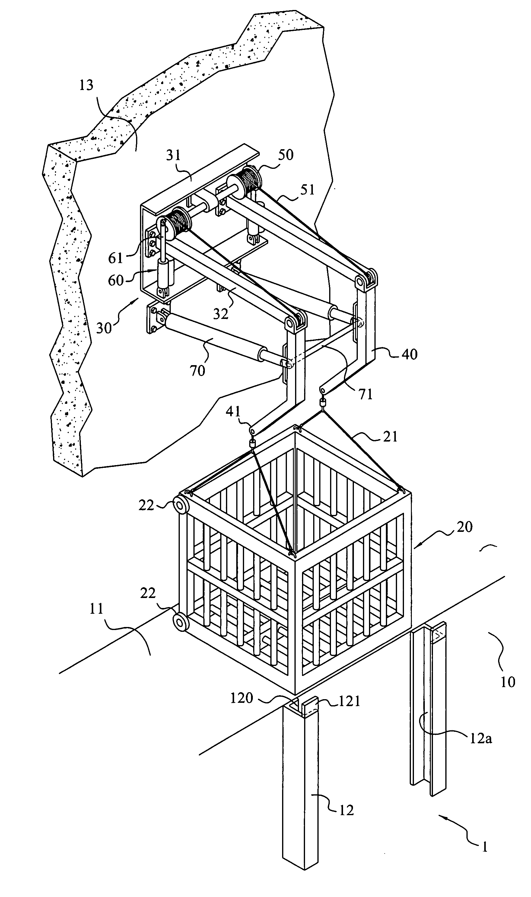
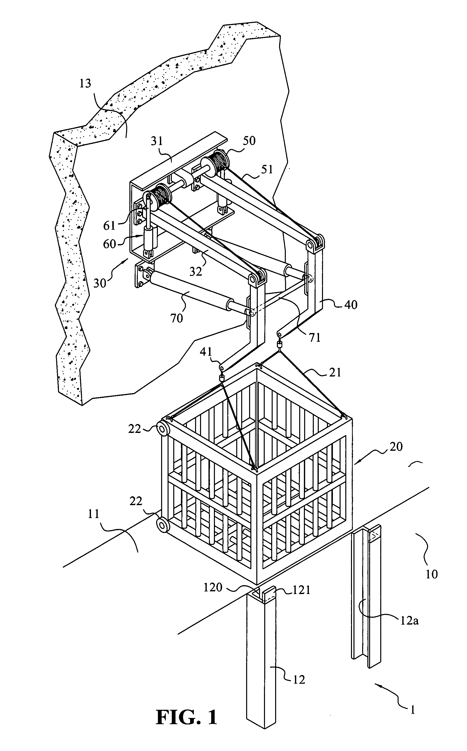
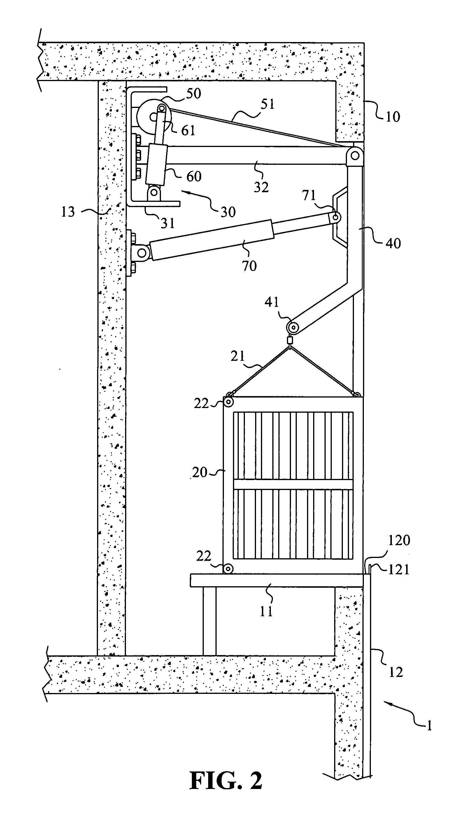
[0040]In FIG. 1-6, the transport equipment of the present invention operated in combination with a building is shown. Generally, building 1 with RC structure basically has a window platform 11 or balcony provided on the outer wall 10 for good lighting, ventilation and landscape. For the sake of safety, iron grille for burglar proof is added in most cases. This invention utilizes the outer wall 10 of the building 1 to transport personnel or commodity in emergency or in need condition. The transport equipment of the present invention mainly comprises a carrier 20 accommodated on the window platform 11 and thus becomes a part of the building, for example, by decorated it identically with the iron grille 20′ to become a part of the iron grille 20′ as shown in FIG. 5. A plurality of suspending cables 21 for sustaining the weight of the carrier 20 are provided on the top of the carrier 20, and at least a pair of pulleys 22 are provided on the bottom.

[0041]A slow descending mechanism 30 is...

second embodiment

[0044]In FIGS. 8 to 10, the transport equipment of the present invention operated in combination with a building having curtain wall is shown. As to a skyscraping building 1 having curtain wall, the raising stroke of the aerial ladder of a fire fighting truck is limited and might be unable to give access to higher floor. On the other hand, the fire fighting regulation requires that escape window 11′ must be provided at some fixed location of each floor. Thus, this invention takes advantage of the escape window 11′ and the curtain wall 10′ to transport personnel and commodity in emergency or in need.

[0045]According to the transport equipment of this embodiment, the basic structure is substantially the same as the above embodiment, therefore repeated description thereof is omitted. The carrier 20 is accommodated in a window platform of an escape window 11′ as a part of building. For example, the carrier 20 has a decoration panel 10a which is almost the same as the curtain glass 101, t...

third embodiment

[0047]In FIGS. 11 and 12, the transport equipment of the present invention operated in combination with a building having curtain wall is shown. The transport equipment in this embodiment has two carriers 20, 20′ alternately moving upward and downward simultaneously along the guide rails provided on the outer wall 10′ of the building 1′ by providing different weights on the carriers connected at both ends of a cable, so that personnel and commodity can be transported in powerless mode.

[0048]According to this invention, a pair of escape windows 11′ are provided respectively at an upper location and a lower location on the outer wall 10′ of the building 1′, and are separated with each other at a suitable transverse distance. A pair of carrier 20, 20′ are accommodated within the respective escape window 11′. A pair of suspending cables 21 are provided on the top of each carrier 20, 20′, and at least a pair of pulleys 22 (not shown in the figures, this part is almost the same as that in...


PUM


Abstract

A transport equipment comprises at least a carrier that is disposed on the window platform or balcony and thus becomes one part of a building in normal condition, or that is pushed out of the window or balcony for personnel and commodity transportation through a cantilever beam of a slow descending mechanism when in need, to descend or ascend along the outer wall of a building. In this manner, personnel or commodity can be transported by the carrier to reach ground directly or in relay-floor connection mode. For example, personnel or precious commodity can be evacuated at the first instant of fire. Even in the case of electricity disconnection due to the happening of a fire, the slow descending mechanism of the transport equipment can be operated by uninterruptible power supply or by hand.

Description

BACKGROUND OF THE INVENTION[0001]1. Field of the Invention[0002]The present invention relates to a transport equipment, more particularly to a transport carrier (simply carrier hereinafter) that is disposed on the window platform or balcony and thus becomes one part of a building in normal condition, and that is pushed out of the window platform or balcony for personnel and commodity transportation through a slow descending mechanism in emergency condition.[0003]2. Brief Description of the Prior Art[0004]Ordinary building is designed to have windows or balcony for good lighting, ventilation and landscape. However, iron grille for burglar proof added in most cases for safety consideration is apt to become an obstacle for escaping in emergency condition, thus great loss in life or property will be suffered.[0005]In order to improve the defect of retardation on escaping caused by the adding of iron grille in traditional building, the inventor of this application has proposed a “BURGLAR...

Claims


Application Information

Patent Timeline
Patent Type & Authority Applications(United States)
IPC IPC(8): E04G3/28E04G3/20
CPCA62B1/02E04G3/30E04G3/28
Inventor TSENG, CHUNG-ENHUNG, YU-HAN
Owner TSENG CHUNG EN
Learn More