Photoelectric encoder and electronic equipment using the same

a technology of photoelectric encoder and encoder, which is applied in the direction of code conversion, discharge tube/lamp details, instruments, etc., can solve the problems of considerable increase in cost, the conventionally impossible use of movable objects b>2/b> made of metal or synthetic resin for large-scale printers, and the limitation of their resolution, etc., to achieve the effect of increasing the total light-reception area, increasing the output strength of detection signals, and wide width

Active Publication Date: 2008-03-06
SHARP KK
View PDF6 Cites 10 Cited by
  • Summary
  • Abstract
  • Description
  • Claims
  • Application Information

AI Technical Summary

Benefits of technology

[0039]As apparent from the above description, in the photoelectric encoder of the present invention, for obtainment of an output having resolution n times (n is an integer, where n≧2) higher than that of the movable object, the light receiving section is made up by arraying 2n light receiving elements at a pitch (1 / 2n)-fold of the array pitch P of the light transmitting / reflecting zones and the light non-transmitting zones of the movable object. Therefore, the array pitch of the light receiving elements can be made two times larger than the array pitch of the light receiving elements of the photoelectric encoder disclosed in JP 2604986 U, so that the required number of light receiving elements can be reduced to a half.
[0040]Accordingly, in the case where neighboring light receiving elements are separated from one another by insensitive material or light non-passing mask or the like, a large width can be ensured as the effective light receiving element width. As a result, the total light-reception area can be increased, the output strength of detection signals can be increased, and thus the S / N ratio can be improved.
[0041]Further, if the value of the integer n is 2, then a two times higher resolution can be obtained even with the use of a movable object having a resolution of 300 dpi equal to the conventional counterpart and light receiving elements each having a width of (¼)P equal to the conventional counterpart. In that case, since the array pitch of the light receiving elements is set to a double of the array pitch of the light receiving elements in the photoelectric encoder disclosed in JP 2604986 U. there can be achieved a reduction in cost.

Problems solved by technology

However, because of limitations of fine processing of these materials, their resolutions are also limited naturally.
As a result, it has conventionally been considered impossible to use the movable object 2 made of metal or synthetic resin for use in large-scale printers.
However, because glass is fragile and liable to breakage, there is a need for ensuring the mechanical strength, which leads to a problem of considerably increased cost.
As a result, the level of the output signals OUT1, OUT2 become smaller, causing the output signal to be easily influenced by crosstalk of signals of adjacent other channels, which may lead to problems of decreases in the S / N ratio of detection signals as well as increases in cost,

Method used


Image

  • Photoelectric encoder and electronic equipment using the same
  • Photoelectric encoder and electronic equipment using the same
  • Photoelectric encoder and electronic equipment using the same

Examples


first embodiment

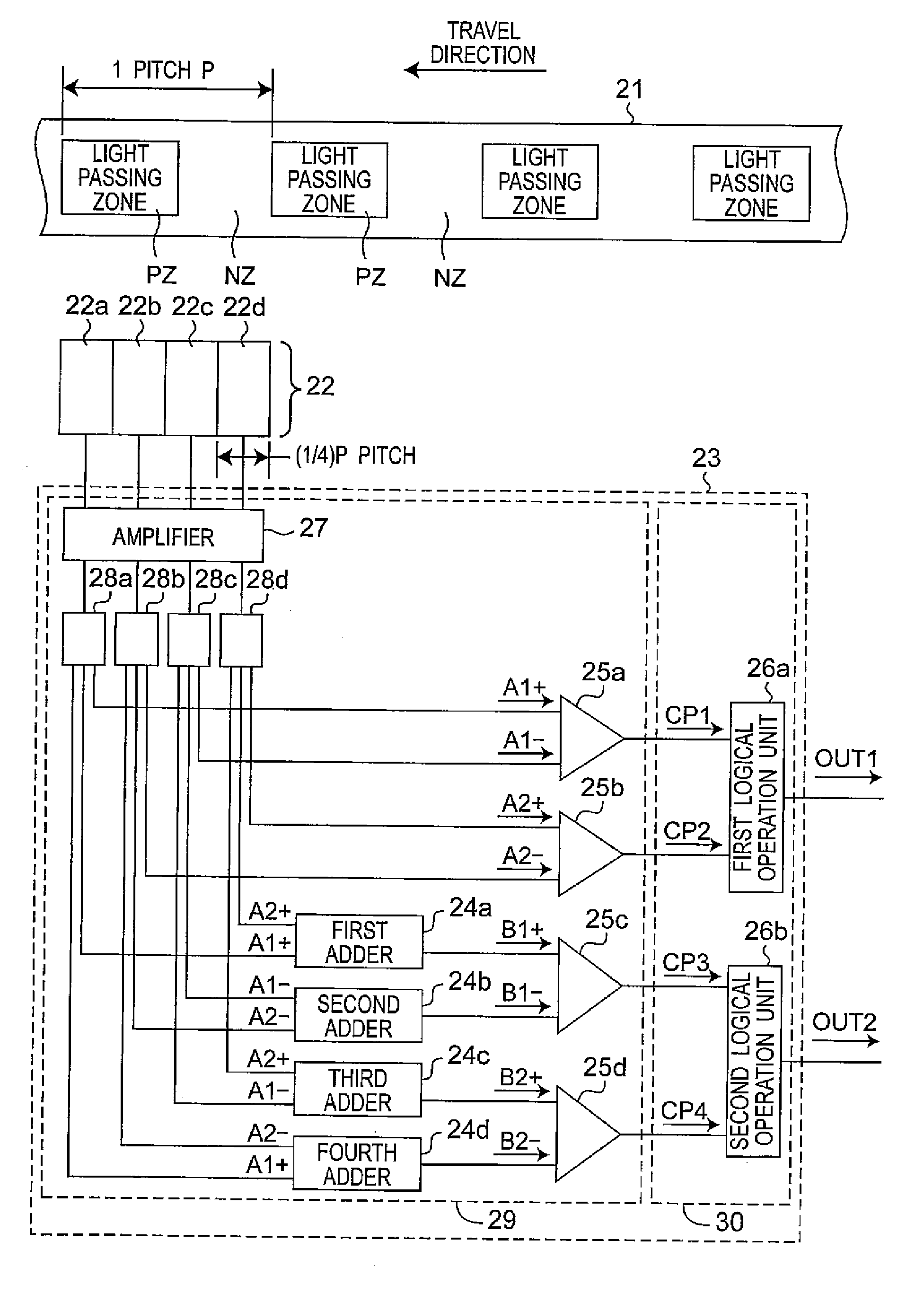
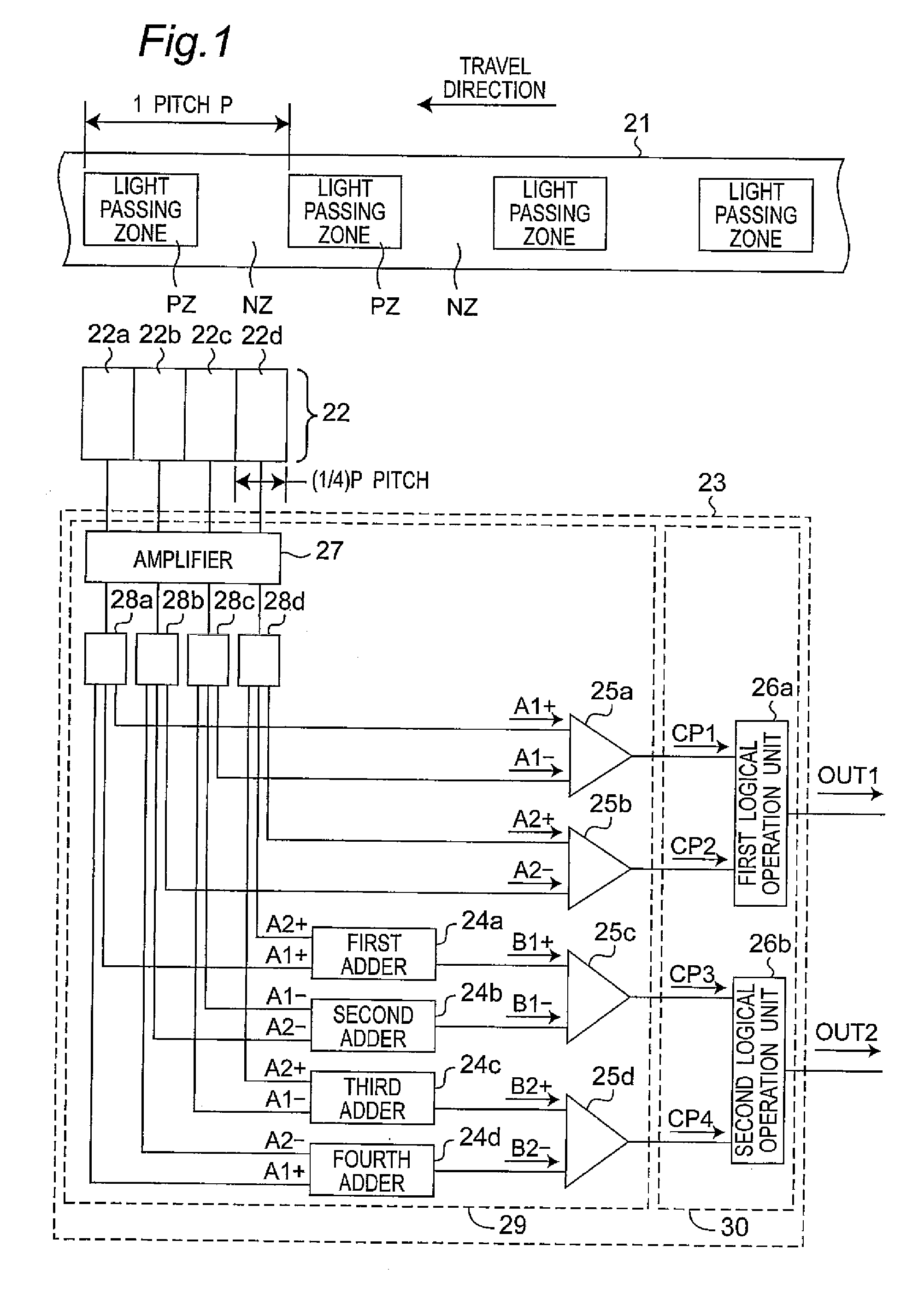
[0057]FIG. 1 shows an outlined configuration of a photoelectric encoder according to this embodiment, including the placement relation between light passing zone PZ and light non-passing zone NZ of a movable object 21 and four light receiving elements 22a-22d constituting a light receiving section 22 and further including the configuration of a signal processing section 23 for calculating output signals of the individual light receiving elements 22a-22d.

[0058]As shown in FIG. 1, this optical encoder includes a light emitting section (not shown), a movable object 21 in which the light passing zone PZ and the light non-passing zone NZ are formed alternately at a constant pitch P along its travel direction, a light receiving section 22 composed of four (2n, where n=2) light receiving elements 22a-22d arrayed on a straight line without clearances at a pitch of (¼)P ((L / 2n)P, where L=1, n=2)) along the travel direction of the movable object 21, and a signal processing section 23 compose...

second embodiment

[0077]FIG. 3 shows an outlined configuration of a photoelectric encoder according to this embodiment. This photoelectric encoder is the same as the photoelectric encoder of the first embodiment shown in FIG. 1 except for a light receiving section 31, and therefore, the same reference numerals as in FIG. 1 are used and its detailed description is omitted. It is noted that this embodiment is intended to explain mostly the contents of claim 5.

[0078]The light receiving section 31 is composed of eight light receiving elements 31a-31h arrayed on a straight line without clearances along the travel direction of the movable object 2 at a pitch of (¼)P ((L / 2n)P, where L=1, n=2). That is, the light receiving section 31 has an arrangement that the light receiving section 22 of the photoelectric encoder of the first embodiment shown in FIG. 1 is arrayed two in number. In this case, the light receiving elements 31e-31h function in the utterly same manner as the light receiving elements 22a-22d (i...

third embodiment

[0079]FIG. 4 shows an outlined configuration of a photoelectric encoder of this embodiment. This photoelectric encoder has a configuration that other circuits are added to the signal processing section 23 of the photoelectric encoder of the first embodiment shown in FIG. 1.

[0080]In the signal processing section 23 of this photoelectric encoder, first, second correction amplifiers 41a, 41b are placed between the signal distributors 28a-28d and the first, second comparators 25a, 25b in the signal processing section 23 of the first embodiment shown in FIG. 1, and third, fourth correction amplifiers 41c, 41d (hereinafter, referred to generically as correction amplifiers 41) are placed between the adders 24a-24d and the third, fourth comparators 25c, 25d. Otherwise, the photoelectric encoder of this embodiment is the same as that of the first embodiment, and therefore the same component parts are designated by the same reference numerals as in FIG. 1 and their detailed description is omi...


PUM


Abstract

In the photoelectric encoder of the invention, as a light passing zone PZ of a movable object 21 travels by one pitch P, an output signal OUT2 of a second logical operation unit 26b comes to be delayed in phase by 45° with respect to an output signal OUT1 of a first logical operation unit 26a. Therefore, an output having a resolution two times higher than that of the movable object having a phase difference of 90° can be obtained, where the width of each of light receiving elements 22a-22d is (¼)P. Accordingly, the width of each of the light receiving elements can be made two times larger, compared with the case where the width of each of the light receiving elements is (⅛)P as in conventional optical encoders. Thus, the output strength of the detection signal can be increased, so that the S/N ratio can be improved.

Description

CROSS-REFERENCE TO RELATED APPLICATIONS[0001]This nonprovisional application claims priority under 35 U.S.C. §119(a) on Patent Application No. 2006-233773 filed in Japan on Aug. 30, 2006 and Patent Application No. 2006-345859 filed in Japan on Dec. 22, 2006, the entire contents of which are hereby incorporated by reference.BACKGROUND OF THE INVENTION[0002]The present invention relates to a photoelectric encoder, as well as electronic equipment using the same, for detecting position, travel speed, travel direction and the like of a movable object by receiving, with a light receiving element, light transmitted or reflected by the movable object.[0003]In printers, plotters, optical disk units and the like, photoelectric encoders are used in a mechanism for detecting displacement or displacement direction of a printing head or an optical head. As this type of photoelectric encoder, conventionally, there has been known a photoelectric rotary encoder disclosed in JP S59-40258 A.[0004]FIG....

Claims


Application Information

Patent Timeline
Patent Type & Authority Applications(United States)
IPC IPC(8): H01J3/14
CPCG01D5/34715G01D5/2451
Inventor SASAKI, MASATOOKADA, NORIKAZU
Owner SHARP KK
Why Eureka
Try Eureka