Light emitting device and the manufacture method thereof

a technology of light-emitting devices and manufacturing methods, which is applied in the manufacture of semiconductor/solid-state devices, semiconductor devices, electrical devices, etc., can solve the problems of reliability problems, heat dissipation, and temperature rise during operation, and achieve the effect of improving the heat dissipation efficiency of light-emitting devices

Active Publication Date: 2008-03-06
EPISTAR CORP
View PDF6 Cites 102 Cited by
  • Summary
  • Abstract
  • Description
  • Claims
  • Application Information

AI Technical Summary

Benefits of technology

[0005]This invention provides a light-emitting element and the manufacture method thereof. The light-emitting element is suitable for flip-chip bonding and comprises an electrode having a plurality of micro-bumps for d

Problems solved by technology

Employing light emitting diode (LED) in high power illumination, besides continuously promoting brightness, heat dissipation is another main problem that is indeed necessary to be solved.
When light extraction efficiency is not good, the light, which cannot pierce a light-emitting device incl

Method used


Image

  • Light emitting device and the manufacture method thereof
  • Light emitting device and the manufacture method thereof
  • Light emitting device and the manufacture method thereof

Examples


Embodiment Construction

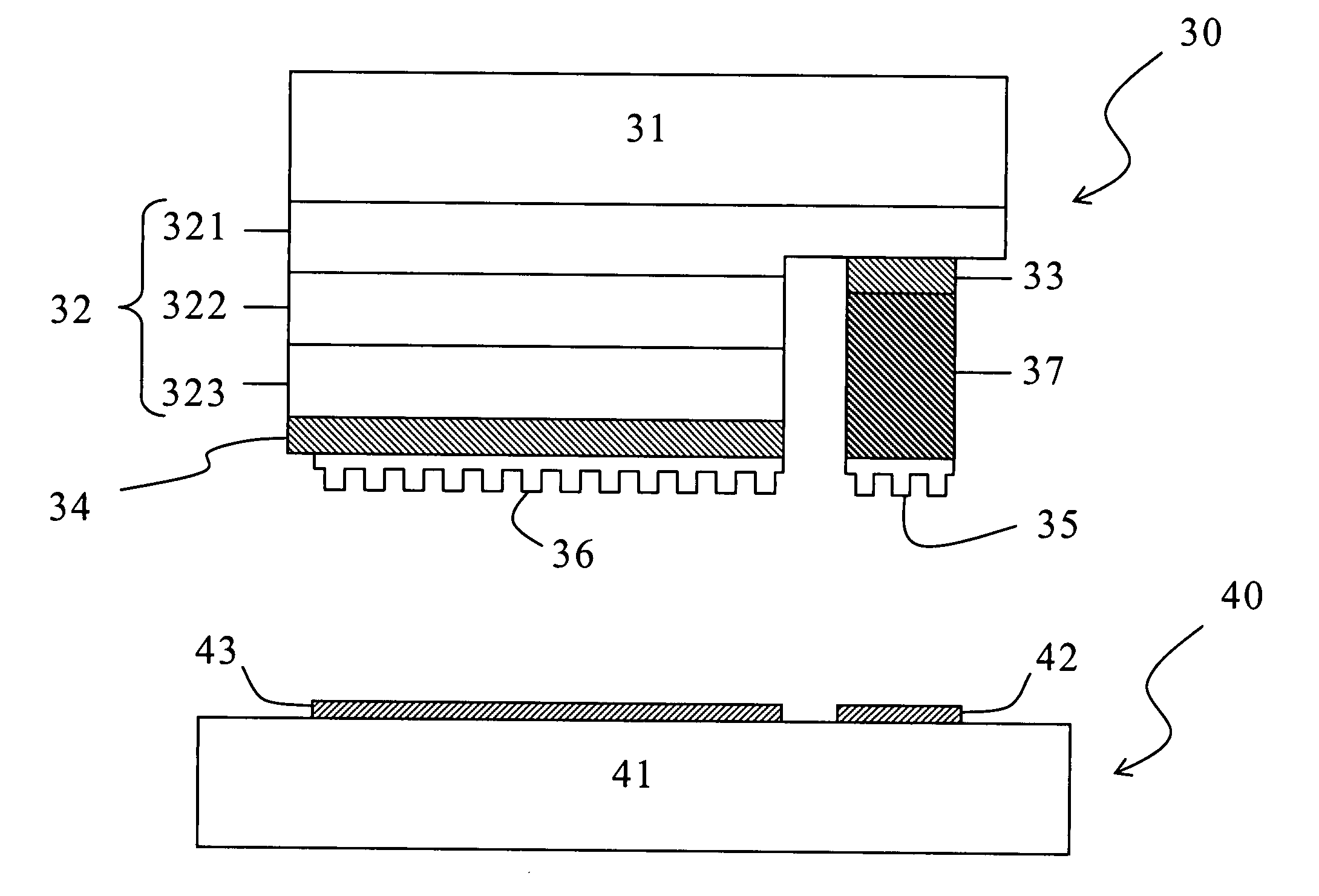
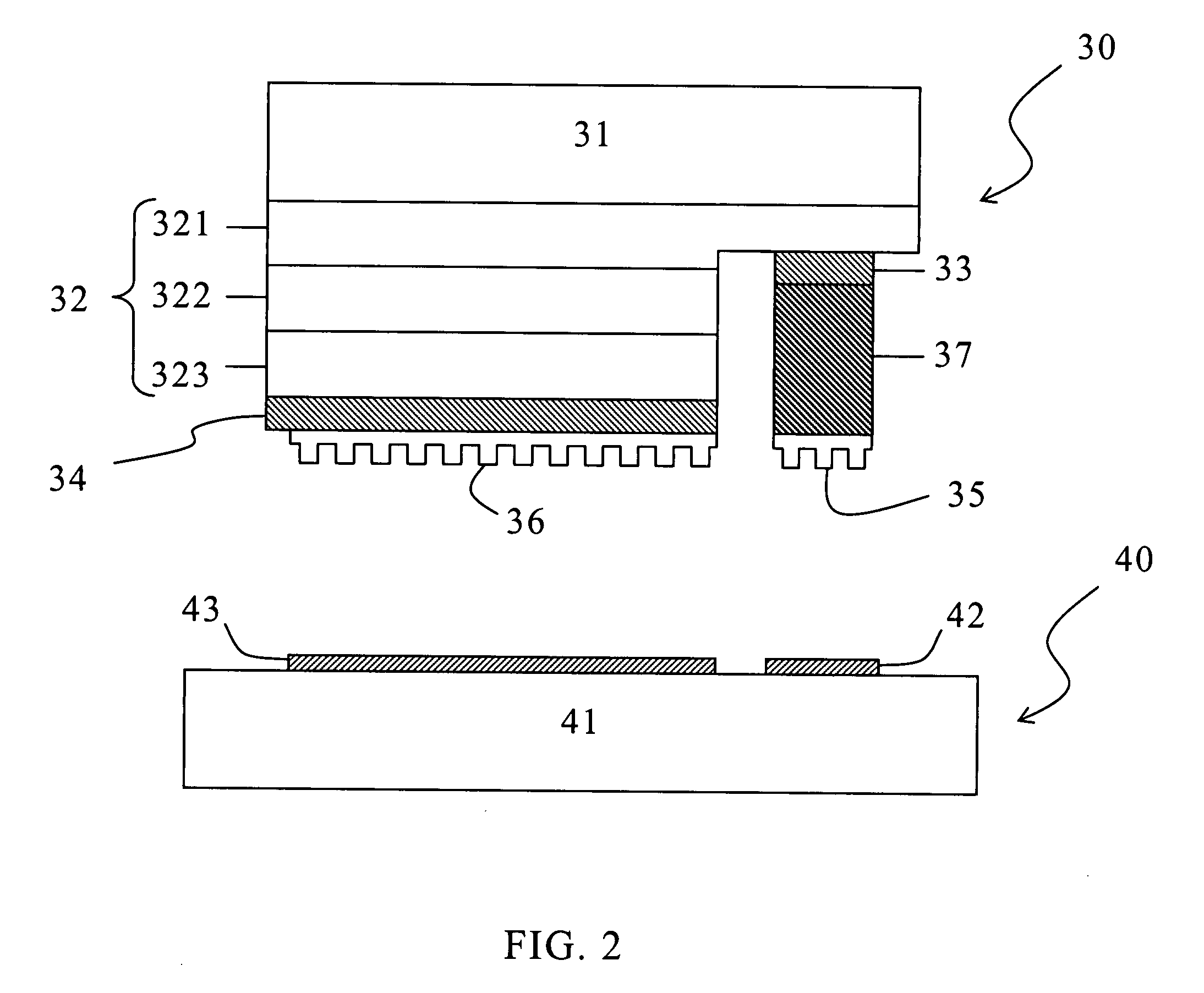
[0017]In FIG. 2, a light-emitting element comprises an LED 30 and a submount unit 40. The LED 30 comprises a transparent substrate 31, a light-emitting stack 32, a first contact layer 32, a second contact layer 33, a first electrode 35, and a second electrode 36. The transparent substrate 31 comprises at least one material selected from the group consisting of Al2O3, GaN, Glass, Gap, Sic, and CVD diamond. The light-emitting stack 32 is formed on the transparent substrate 31 and emits light when receiving a forward voltage. Color of the light depends on the material of the light-emitting stack 32. For example, the material of (AlzGa1-x)0.5In0.5P series can emit red light, yellow light, or green light in accordance with the value of z. The material of AlxInyGa(1-x-y)N series can emit blue light or purple light in accordance with the combination of the value of x and y. The light-emitting stack 32 comprises a first electricity semiconductor layer 321, an active layer 322, and a second ...


PUM


Abstract

This invention provides a light-emitting element and the manufacture method thereof. The light-emitting element is suitable for flip-chip bonding and comprises an electrode having a plurality of micro-bumps for direct bonding to a submount. Bonding within a relatively short distance between the light-emitting device and the submount can be formed so as to improve the heat dissipation efficiency of the light-emitting device.

Description

REFERENCE TO RELATED APPLICATION[0001]The present application claims the right of priority based on Taiwan Application Serial Number 095132845, filed on Sep. 5, 2006, the disclosure of which incorporated herein by reference in its entirety.TECHNICAL FIELD[0002]The present invention relates to a light-emitting element, and more particularly, to a light-emitting element comprising an electrode comprising a plurality of micro-bumps.BACKGROUND[0003]Employing light emitting diode (LED) in high power illumination, besides continuously promoting brightness, heat dissipation is another main problem that is indeed necessary to be solved. When light extraction efficiency is not good, the light, which cannot pierce a light-emitting device including LED and its encapsulant, transforms into heat. If the heat cannot be dissipated out of the light-emitting device effectively, the temperature is going to raise during operation. Thus, reliability problem comes out. Prior arts provide a lot of method...

Claims


Application Information

Patent Timeline
IPC IPC(8): H01L33/00H01L33/38H01L33/62
CPCH01L33/20H01L33/38H01L2224/16H01L2933/0016H01L33/62H01L24/05H01L24/08H01L2224/05001H01L2224/05023H01L2224/05557H01L2224/05568H01L2224/05573H01L2224/08238H01L2924/00014H01L2224/05599H01L2224/05099
Inventor SHIEH, YUH-RENFAN, HSUAN-CHENGLIN, JIN-YWANHSU, CHUNG-YIHUANG, CHUNG-KUEI
Owner EPISTAR CORP
Why Eureka
Try Eureka