Method and system for dynamic frequency adjustment during video decoding

Inactive Publication Date: 2008-03-06
NVIDIA CORP
View PDF12 Cites 40 Cited by
  • Summary
  • Abstract
  • Description
  • Claims
  • Application Information

AI Technical Summary

Benefits of technology

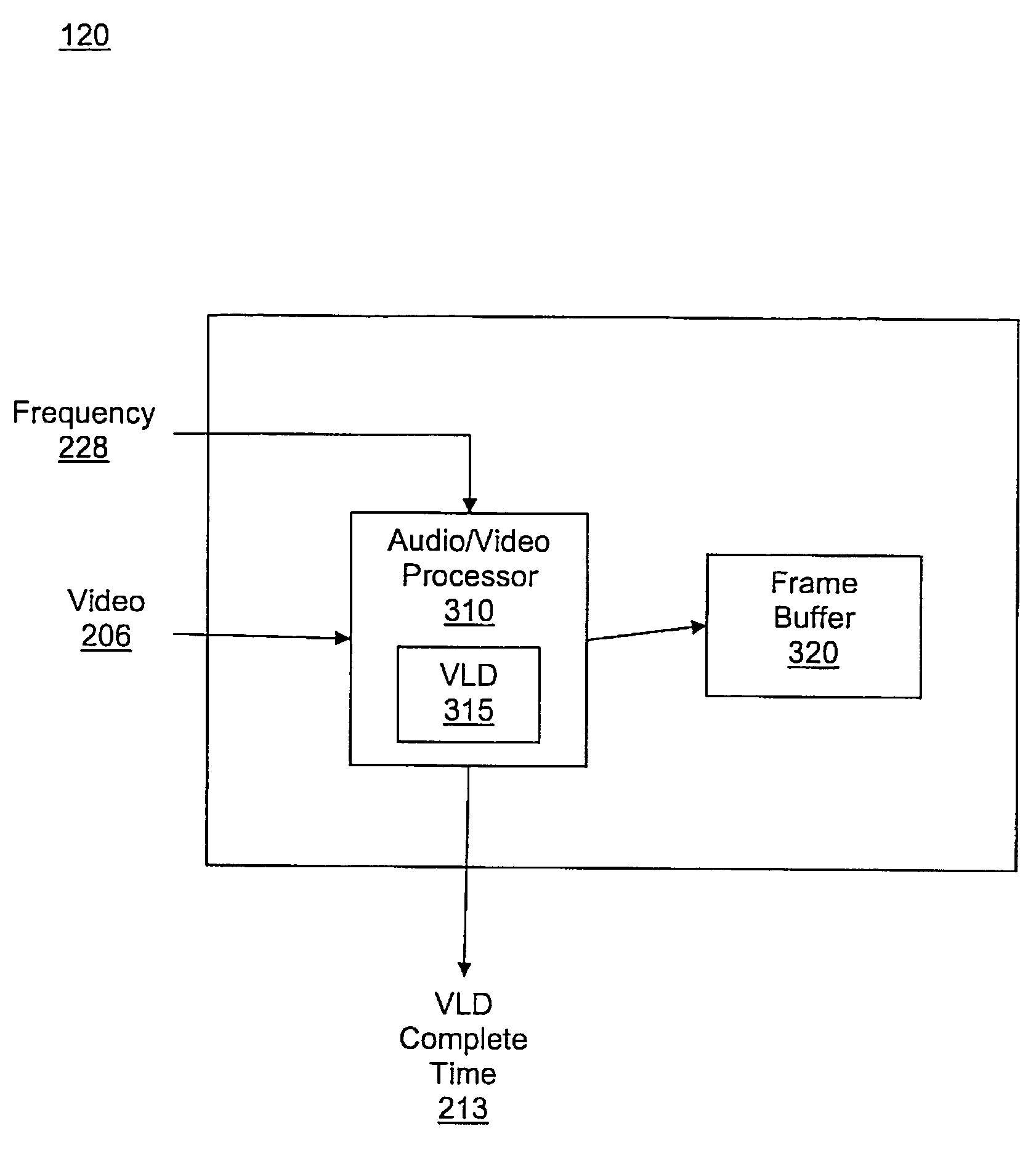
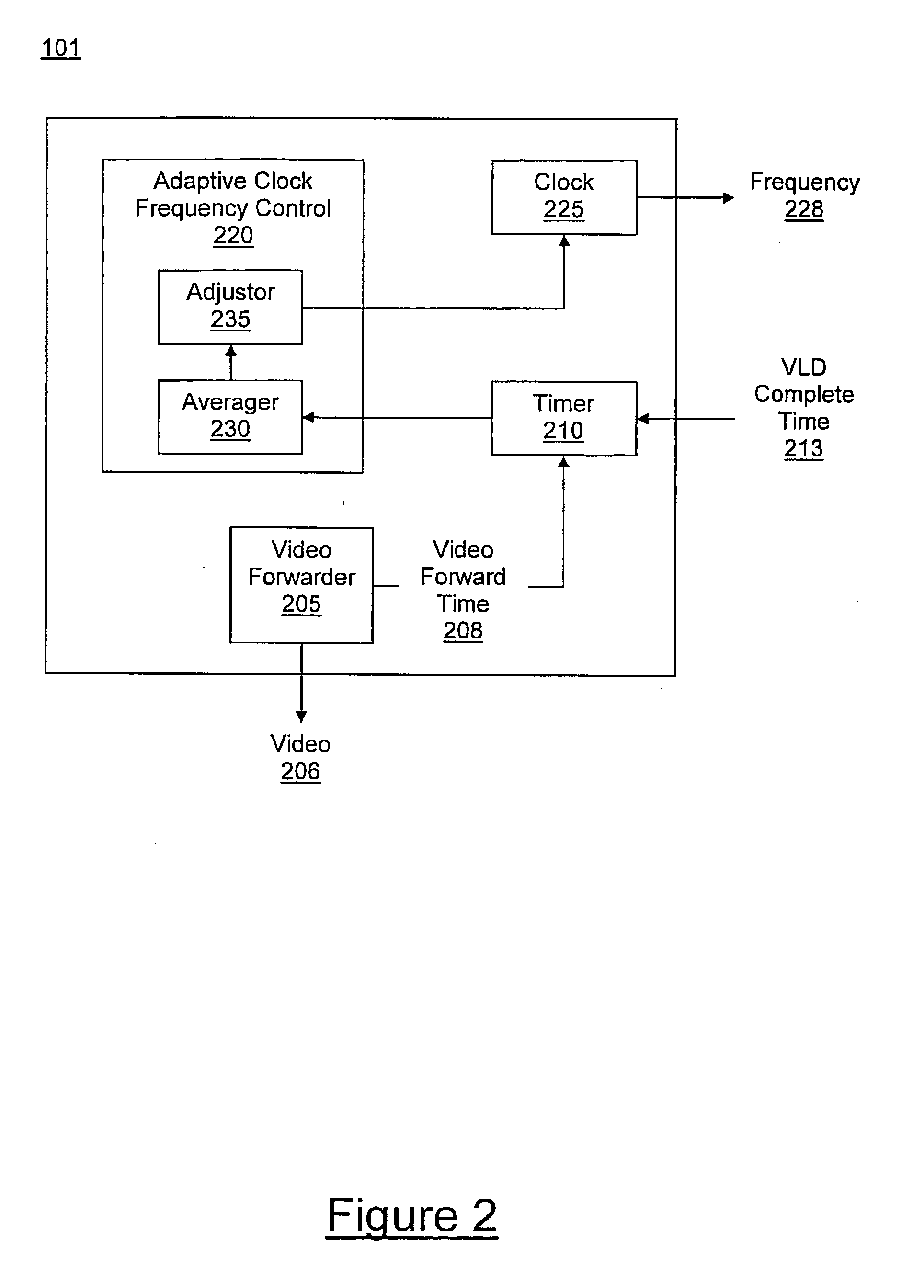
[0005]Embodiments of the present invention provide for dynamic frequency adjustment during video decoding. Embodiments of the present invention are capable of adaptively adjusting the frequency of an audio / video processor (AVP) during video decoding. Embodiments of the present invention provide for reducing power consumption of an AVP by reducing unused processing frequency.

Problems solved by technology

MPEG and H.264 video encoding is complex, and there may be variations in the bit rate depending on the compression ratio.
In other words, frames of video may require variable amounts of processing time in performing the VLD operation.
In particular, typical hardware video decoding systems do not provide for changing frequency operating an AVP during a video decode operation.
For hardware video decoding systems implemented within a computer system having a constant power supply, such as a desktop computer, clocking the AVP at the highest frequency results in reduced usage time, but also results in increased power consumption.
However, a typical hardware video decoding system implemented within a battery-powered portable computing device, where the AVP consumes the power required to decode a worst case video clip even for video clips not requiring decoding at such a high frequency, will suffer excess and unnecessary power consumption.
The excess power consumption effectively reduces the usage time for the portable computing device, as the battery will require recharging sooner.
Moreover, while other hardware video decoding systems use clock gating to conserve power, the clock tree of these systems continues to toggle, also resulting in excessive and unnecessary power consumption.

Method used


Image

  • Method and system for dynamic frequency adjustment during video decoding
  • Method and system for dynamic frequency adjustment during video decoding
  • Method and system for dynamic frequency adjustment during video decoding

Examples


Embodiment Construction

[0017]Reference will now be made in detail to the preferred embodiments of the present invention, examples of which are illustrated in the accompanying drawings. While the invention will be described in conjunction with the preferred embodiments, it will be understood that they are not intended to limit the invention to these embodiments. On the contrary, the invention is intended to cover alternatives, modifications and equivalents, which may be included within the spirit and scope of the invention as defined by the appended claims. Furthermore, in the following detailed description of embodiments of the present invention, numerous specific details are set forth in order to provide a thorough understanding of the present invention. However, it will be recognized by one of ordinary skill in the art that the present invention may be practiced without these specific details. In other instances, well-known methods, procedures, components, and circuits have not been described in detail ...


PUM


Abstract

A method and system for dynamic frequency adjustment during video decoding. A decode time for performing a hardware variable length decode (VLD) on a portion of a video clip at a processor is measured. A frequency controlling the processor during video decoding is adjusted based at least in part on the decode time.

Description

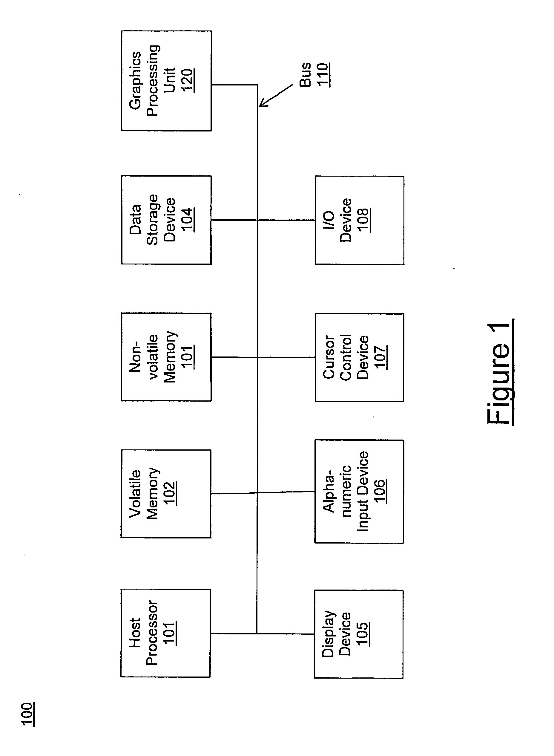
FIELD OF THE INVENTION[0001]The field of the present invention pertains to video decoding. More particularly, the present invention relates to method of dynamic frequency adjustment during video decoding.BACKGROUND OF THE INVENTION[0002]Many video standards, such as Moving Pictures Experts Group (MPEG) standards, e.g., MPEG-3 and MPEG-4, and the H.264 standard, include a variable length decode (VLD) operation during a video decode. In a hardware video decoder, the VLD operation may be executed at a particular processor, such as an audio / video processor (AVP). MPEG and H.264 video encoding is complex, and there may be variations in the bit rate depending on the compression ratio. Variations in bit rate cause fluctuations in how fast the AVP needs to be clocked in performing the VLD operation. In other words, frames of video may require variable amounts of processing time in performing the VLD operation.[0003]In a typical hardware video decoding system, VLD operations are performed by...

Claims


Application Information

Patent Timeline
IPC IPC(8): H04N11/04H04N11/02H04N19/00
CPCH04N19/91H04N19/42H04N19/44
Inventor NEWLIN, JOHN B.TJANDRASUWITA, BENEDICTUS I.
Owner NVIDIA CORP
Why Eureka
Try Eureka