Reducing thermal load on optical head

a technology of thermal load and optical head, applied in the field of lasers and optical amplifiers, can solve the problems of unconverted input light as waste light, waste light may contribute to an undesirable build-up of heat in the optical system, adversely affect the performance of the optical system, etc., and achieve the effects of reducing the fluence level of waste light, avoiding damage, and significantly reducing thermal load on the optical head

Active Publication Date: 2008-03-06
DISCO CORP
View PDF48 Cites 44 Cited by
  • Summary
  • Abstract
  • Description
  • Claims
  • Application Information

AI Technical Summary

Benefits of technology

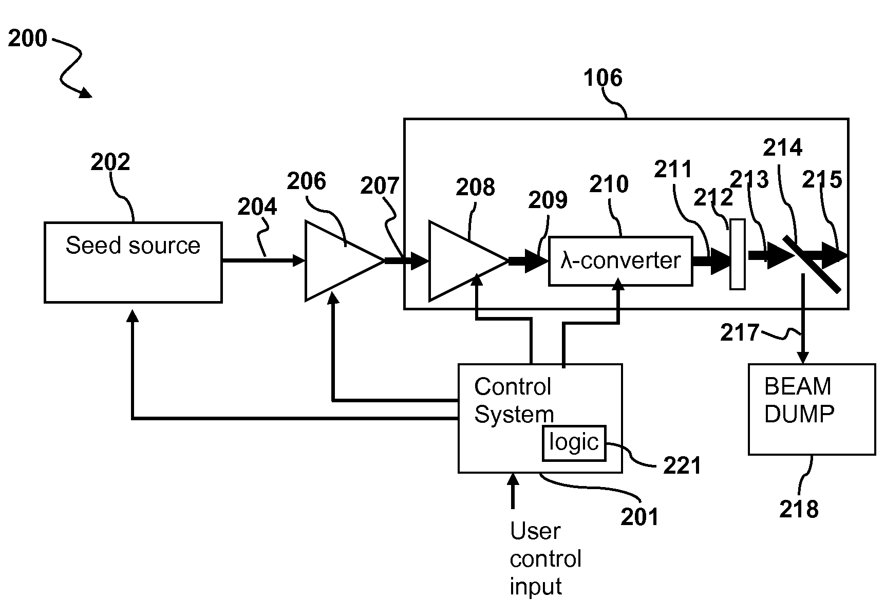
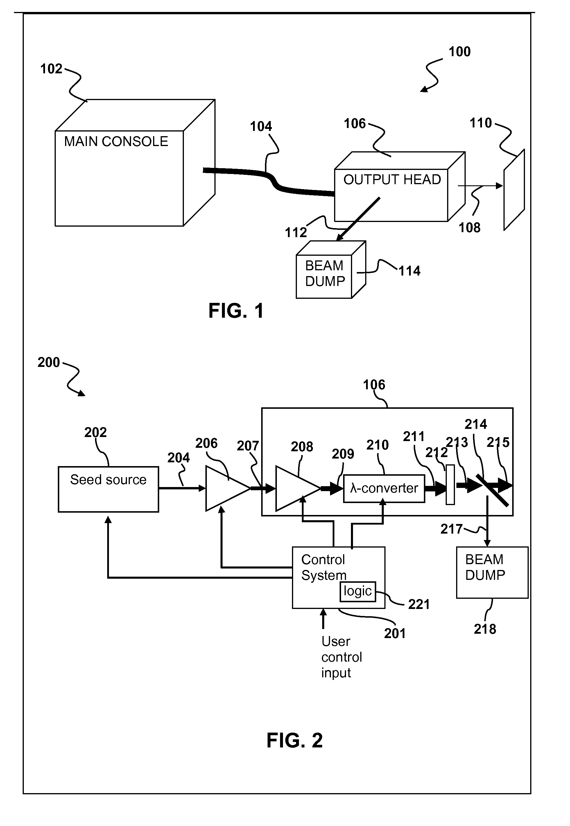
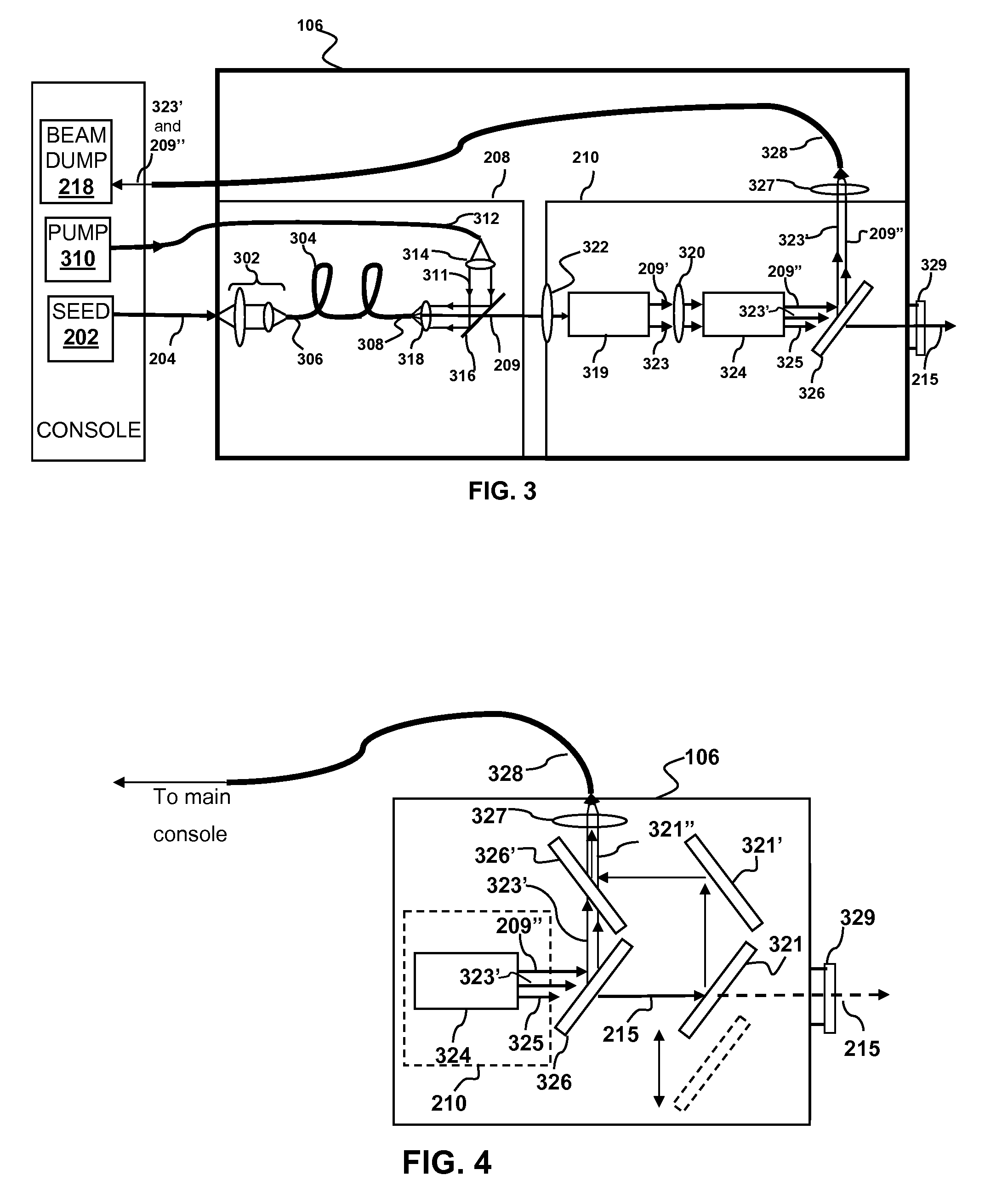
[0060]The captured waste light may be delivered to the beam dump by a large diameter multimode fiber. By deflecting the waste light to a thermally isolated beam dump, thermal loads on the optical head may be significantly reduced. The return line fiber (sometimes referred to herein as a waste light fiber) transports the waste light to a location remote (e.g., thermally isolated) from where unwanted light is generated. Typically the waste light is transported to a location remote from the optical head. Unwanted light may be absorbed along the length of the waste light fiber, directed to a beam dump in a main console, or directed to another location where heat is dissipated.
[0061]There are a number of different methods to couple waste light into a fiber. For example, the waste light may be directly coupled into the fiber. Such coupling is appropriate, e.g., if the beam diameter of the waste light is smaller than the diameter of the fiber. Alternatively, coupling with an appropriate lens may be used. For example, a converging lens may be appropriate if the beam diameter of the waste light is larger than the fiber diameter. A diverging lens may be appropriate if the beam diameter is smaller than the fiber diameter. The use of a diverging lens may also reduce the fluence level of the waste light on the fiber end face to avoid damage. In some situations, a tapered fiber may be used to couple waste light to the fiber. The tapered fiber may be either a converging or diverging taper. Tapered fibers may be used in a manner similar to fiber coupling with a lens.

Problems solved by technology

As such, some unconverted input light may remain as waste light.
Such waste light may contribute to an undesirable build up of heat in the optical system.
The build up of heat may adversely affect the performance of the optical system.
This can complicate removal of heat by conventional methods such as conduction or convection.

Method used


Image

  • Reducing thermal load on optical head
  • Reducing thermal load on optical head
  • Reducing thermal load on optical head

Examples


Embodiment Construction

[0013]Although the following detailed description contains many specific details for the purposes of illustration, anyone of ordinary skill in the art will appreciate that many variations and alterations to the following details are within the scope of the invention. Accordingly, the exemplary embodiments of the invention described below are set forth without any loss of generality to, and without imposing limitations upon, the claimed invention.

GLOSSARY

[0014]As used herein:

[0015]The indefinite article “A”, or “An” refers to a quantity of one or more of the item following the article, except where expressly stated otherwise.

[0016]Beam splitter refers to an optical device capable of splitting a beam of light into two or more parts.

[0017]Brillouin scattering refers to a nonlinear optical phenomenon involving spontaneous scattering of light in a medium due to interaction between the light and sound waves passing through the medium.

[0018]Cavity or Optically Resonant Cavity refers to an ...


PUM


Abstract

Methods and apparatus for reducing a thermal load on an optical head are described. Waste light is captured at one or more locations in the optical head and directed to a location that is thermally isolated from the one or more locations in the optical head using or more optical fibers.

Description

FIELD OF THE INVENTION[0001]This invention generally relates to lasers and optical amplifiers and more particularly to thermal management in wavelength converted optical systems.BACKGROUND OF THE INVENTION[0002]High-powered optical sources have many applications in which an intense beam of light is focused onto a substrate or other target. In many high-power optical source architectures, a signal from a seed source is fed into an optical amplifier that amplifies the power of the signal. One example, among others, of such a high-power optical source architecture is referred as a master oscillator, power amplifier (MOPA) architecture. The MOPA architecture allows precise pulsing of the amplified output. Laser systems based on optical amplification of seed signals are often used in high power applications, such as laser micromachining.[0003]Many high power optical systems make use of wavelength conversion to produce light having a desired wavelength or range of wavelengths. Often the p...

Claims


Application Information

Patent Timeline
Patent Type & Authority Applications(United States)
IPC IPC(8): G02B6/26
CPCG02B6/4296H01S3/005H01S3/0092H01S3/06758H01S3/0078G02B6/00
Inventor BYER, MARK W.LEONARDO, MANUEL J.
Owner DISCO CORP
Why Eureka
Try Eureka