Magnetically coupleable robotic surgical devices and related methods

a robotic surgical device and magnetic couple technology, applied in the field of magnetic coupleable robotic surgical devices, can solve the problems of limited scope and complexity of known laparoscopic technology, affecting the efficiency of surgical procedures, and affecting the accuracy of surgical procedures

Active Publication Date: 2008-03-06
BOARD OF RGT UNIV OF NEBRASKA
View PDF101 Cites 173 Cited by
  • Summary
  • Abstract
  • Description
  • Claims
  • Application Information

AI Technical Summary

Problems solved by technology

However, known laparoscopy technologies are limited in scope and complexity due in part to 1) mobility restrictions resulting from using rigid tools inserted through access ports, and 2) limited visual feedback.
That is, long rigid laparoscopic tools inserted through small incisions in the abdomen wall limit the surgeon's range of motion and therefore the complexity of the surgical procedures being performed.
Similarly, using a 2-D image from a typically rigid laparoscope inserted through a small incision limits the overall understanding of the surgical environment.
However, da Vinci® is still restricted by the access ports.
Further disadvantages include the size and high cost of the da Vinci® system, the fact that the system is not available in most hospitals and the system's limited sensory and mobility capabilities.
In addition, most studies suggest that current robotic systems such as the da Vinci® system offer little or no improvement over standard laparoscopic instruments in the performance of basic skills.
Further, the da Vinci® system and similar systems are implemented from outside the body and will therefore always be constrained to some degree by the limitations of working through small incisions.
For example, these small incisions do not allow the surgeon to view or touch the surgical environment directly, and they constrain the motion of the endpoint of the tools and cameras to arcs of a sphere whose center is the insertion point.

Method used


Image

  • Magnetically coupleable robotic surgical devices and related methods
  • Magnetically coupleable robotic surgical devices and related methods
  • Magnetically coupleable robotic surgical devices and related methods

Examples


example 1

[0338] One factor to consider in the development of the mobile robotic devices was the amount of torque needed to move the device.

[0339] To calculate the needed torque, a free-body diagram of the robot sitting motionless on a slope was used to calculate the torque required to keep the robot stationary on the slope. This calculation would be the stall torque that the motor would need (provided that the friction of the surface was enough to prevent the wheels from slipping). The free-body diagram is shown below in FIG. 29.

[0340] From this free-body diagram the following equations were written:

(W sin θ)r=(ma)+Iα+τ

W sin θ−f=ma

W cos θ=N

[0341] This results in the following:

τ=(W sin θ)r

[0342] where [0343] W is the weight of the cylinder, [0344]θ is the angle of the slope, [0345] r is the radius of the cylinder, [0346] m is the mass of the cylinder, [0347] a is the acceleration of the cylinder, [0348] I is the moment of inertia of the cylinder, [0349]α is the angular acceleration of ...

example 2

[0370] In this example, a velocity analysis was performed on a manipulator arm for a mobile robot, according to one embodiment discussed above.

[0371] When performing such an analysis, it was helpful to define a matrix quantity called the Jacobian. The Jacobian specifies a mapping from velocities in joint space to velocities in Cartesian space. The Jacobian can be found for any frame and it can be used to find the joint torques, discussed infra.

[0372]FIG. 7B depicts a schematic of the manipulator used to find the Jacobian in this example. For additional information on the Jacobian, see “Introduction to Robotics” by John J. Craig.

[0373] The fundamental equations used in finding the Jacobian are: Vi+1i+1⁢=i+1⁢ i⁢R·(Vii+ωii⨯Pi+1i)ωi+1i+1⁢=i+1⁢ i⁢R·ωii+θ.i+1·Zi+1i+1 i⁢V⁢=i⁢J⁡(θ)⁢θ.01⁢R=[c⁢ ⁢θ1-s⁢ ⁢θ20s⁢ ⁢θ1c⁢ ⁢θ10001]⇒10⁢R=[c⁢ ⁢θ1s⁢ ⁢θ10-s⁢ ⁢θ1c⁢ ⁢θ10001]12⁢R=[0-1000-1100]·[c⁢ ⁢θ2-s⁢ ⁢θ20s⁢ ⁢θ2c⁢ ⁢θ20001]=[-s⁢ ⁢θ2-c⁢ ⁢θ2000-1c⁢ ⁢θ2-s⁢ ⁢θ20]⇒⁢21⁢R=[-s⁢ ⁢θ20c⁢ ⁢θ2-c⁢ ⁢θ20-s⁢ ⁢θ20-10]23...

example 3

Methods and Materials

[0526] The goal of the current study is to demonstrate the capability of introducing a mobile robot into the abdominal cavity through the esophageal opening.

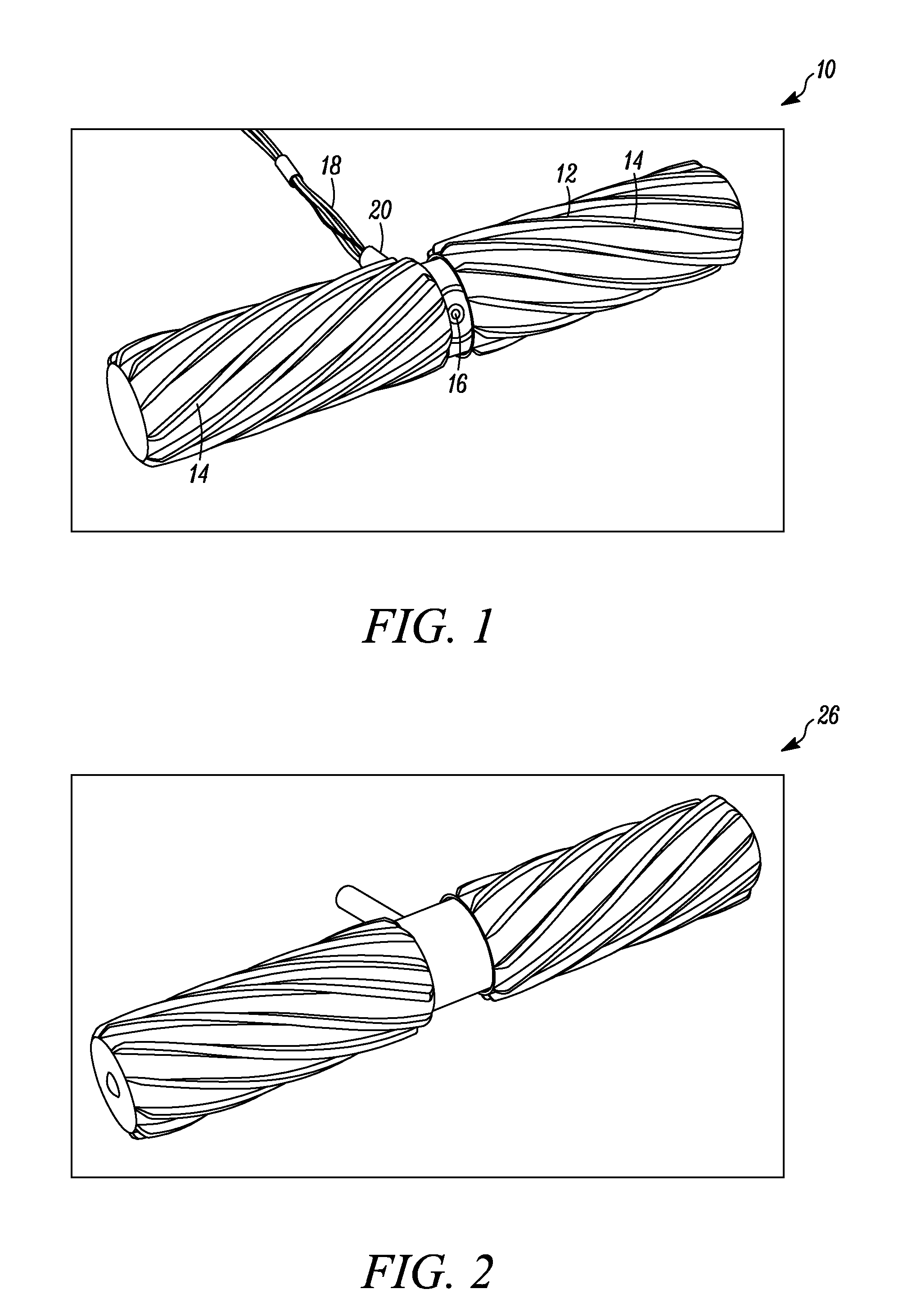
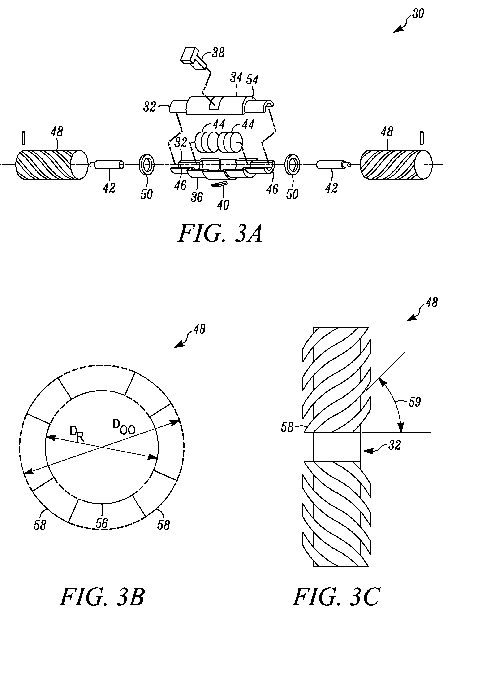
[0527] In this study we used the mobile robotic device depicted in FIG. 45, which was capable of transgastric exploration under esophagogastroduodenoscopic (EGD) control. The robot was 12 mm in diameter and 35 mm long. The helical wheel profile provided sufficient traction for mobility without causing tissue damage. Two independent motors controlled the wheels, thereby providing forward, backward, and turning capability. The robot tail prevented the counter-rotation of the robot's body when the wheels were turning. The entire length of the robot was 75 mm. This robot was tethered for power during the porcine surgery.

[0528] An anesthetized pig was used as the animal model. The 60 lb. pig was fed Gatorade and water for 36 hours prior to the procedure. A sterile overtube was advanced into the pig's stomach w...


PUM


Abstract

The present invention relates to magnetically coupleable robotic surgical devices. More specifically, the present invention relates to robotic surgical devices that can be inserted into a patient's body and can be positioned within the patient's body using an external magnet.

Description

CROSS-REFERENCE TO RELATED APPLICATION(S) [0001] This application claims priority to U.S. Provisional Patent Application Ser. No. 60 / 815,741, filed Jun. 22, 2006, U.S. Provisional Patent Application Ser. No. 60 / 845,603, filed Sep. 19, 2006, U.S. Provisional Patent Application Ser. No. 60 / 868,030, filed Nov. 30, 2006, U.S. Provisional Patent Application Ser. No. 60 / 884,792, filed Jan. 12, 2007, and U.S. Provisional Patent Application Ser. No. 60 / 888,182, filed Feb. 5, 2007, all of which are hereby incorporated herein by reference in their entirety.FIELD OF THE INVENTION [0002] The present invention relates to various embodiments of robotic devices for use in laparoscopic surgery. Specifically, these robotic devices can be inserted into a surgical subject for use in various surgical procedures, providing for performance of various procedures and / or viewing of the area in which a procedure is being performed. BACKGROUND OF THE INVENTION [0003] Laparoscopy is minimally invasive surgery ...

Claims


Application Information

Patent Timeline
Patent Type & Authority Applications(United States)
IPC IPC(8): A61B19/00
CPCA61B1/00158Y10S901/19A61B1/313A61B5/05A61B5/062A61B5/073A61B5/416A61B10/06A61B19/22A61B19/2203A61B19/5212A61B2017/00398A61B2017/00876A61B2017/22082A61B2019/2215A61B2019/2249A61B2019/2253A61B2019/465A61M5/14276A61M5/1452A61M5/16827A61M31/00A61M2205/3523A61M2205/3569B25J5/00B25J7/00Y10S901/01Y10S901/15A61B1/041A61B2034/302A61B34/73A61B2034/2057A61B34/20A61B34/70A61B90/361A61B34/30A61B34/72A61B2090/065B33Y80/00A61B10/04A61B18/00A61B2018/00595A61B2018/00994A61B2560/0462
Inventor FARRITOR, SHANE M.RENTSCHLER, MARKDUMPERT, JASONPLATT, STEPHEN R.OLEYNIKOV, DMITRY
Owner BOARD OF RGT UNIV OF NEBRASKA
Why Eureka
Try Eureka