Mechanical tissue morcellator

a morcellator and mechanical technology, applied in the field of tissue removal devices, can solve the problems of serious harm or injury to the patient, and reducing the size of the entry incision, so as to facilitate the surgeon's operation and manipulation of the morcellator, and prevent unintended movement.

Inactive Publication Date: 2008-03-06
VOSOUGH KHASHAYAR
View PDF11 Cites 42 Cited by
  • Summary
  • Abstract
  • Description
  • Claims
  • Application Information

AI Technical Summary

Benefits of technology

[0010]In accordance with the present invention there is provided an improved mechanical morcellator, which is operable to fragment and aspirate tissue, having a moveable and / or retractable protective guards to allow proper positioning and prevent unintended movement. In addition, the mechanical morcellator of the present invention provides the various functional and structural features in an ergonomically designed “pistol grip” handle which facilitates the surgeon's operation and manipulation of the morcellator.

Problems solved by technology

Nonetheless, even with such surgical technique, the entry incision must still be sized to allow removal of the severed tissue and, therefore, the reduction in entry incision size is rather limited even in more modern or recently developed surgical procedures.
However, the problem with the mechanical morcellator described in this U.S. patent and other non-patented mechanical morcellators currently on the market is that there is the possibility of causing severe harm or injury to the patient if the blade of the morcellator moves beyond the tissue which is to be removed.
That is, healthy tissue could be injured or destroyed resulting in serious harm or injury to a patient should the morcellator move beyond the tissue to be removed.

Method used


Image

  • Mechanical tissue morcellator
  • Mechanical tissue morcellator
  • Mechanical tissue morcellator

Examples


Embodiment Construction

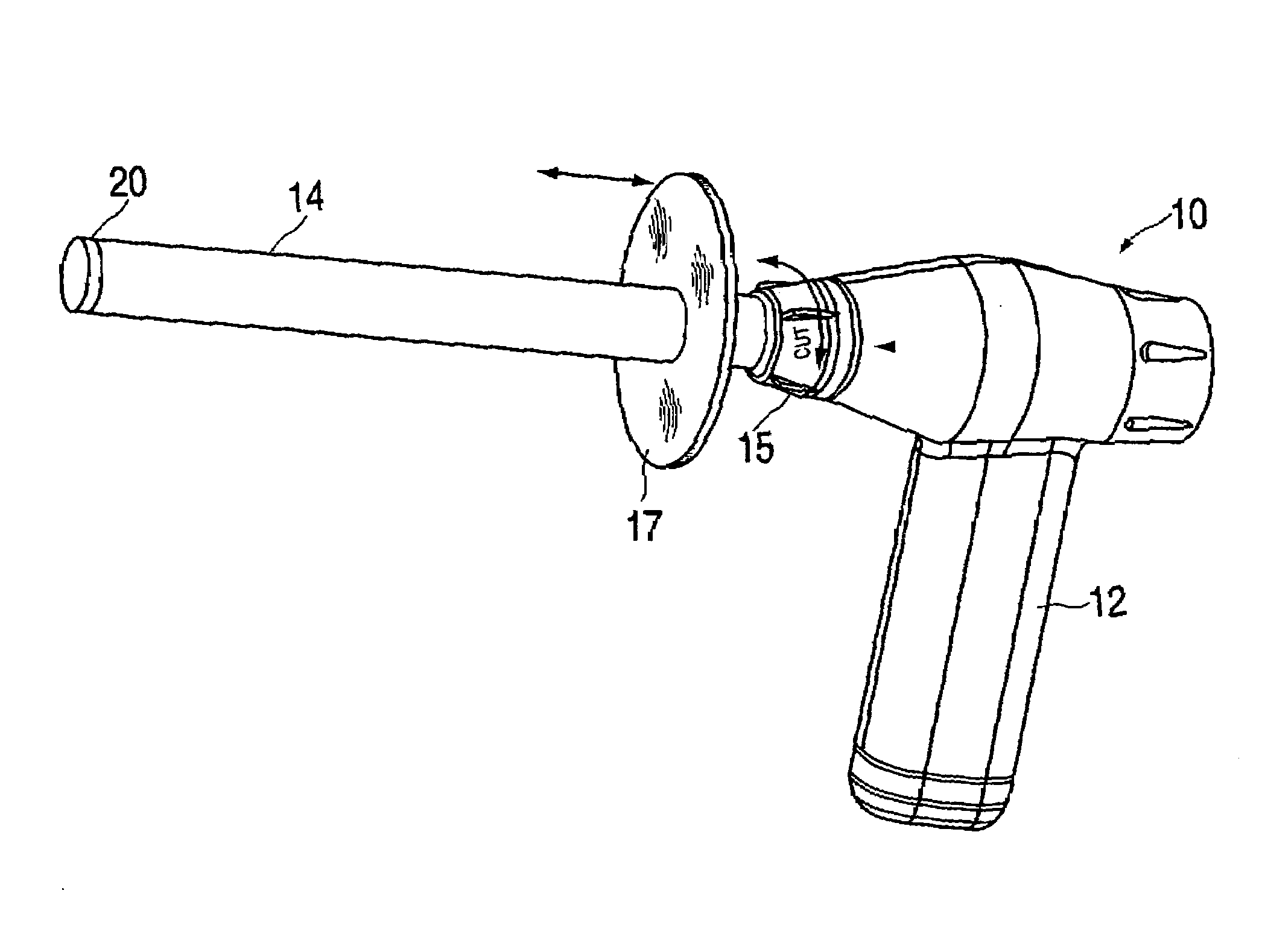
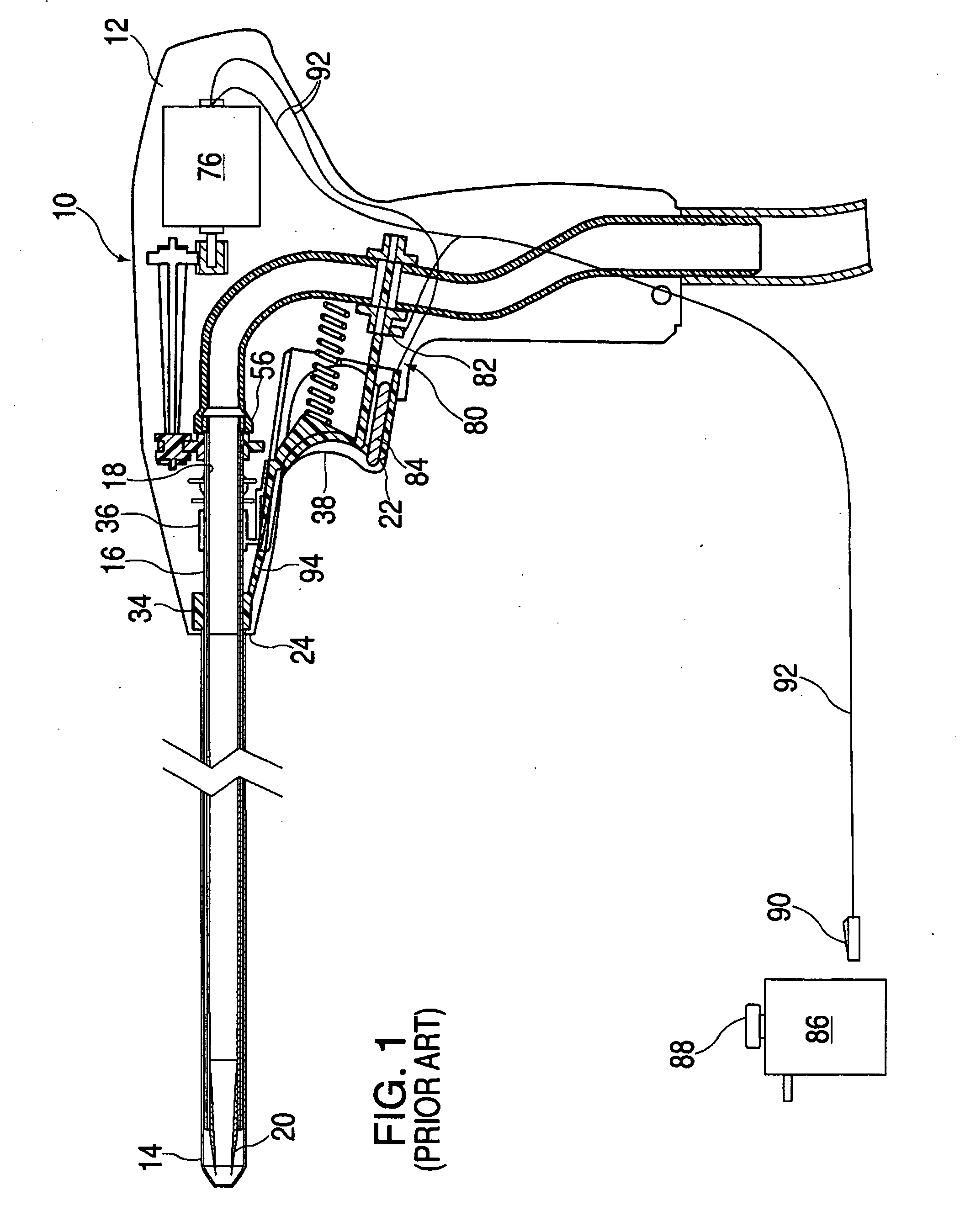
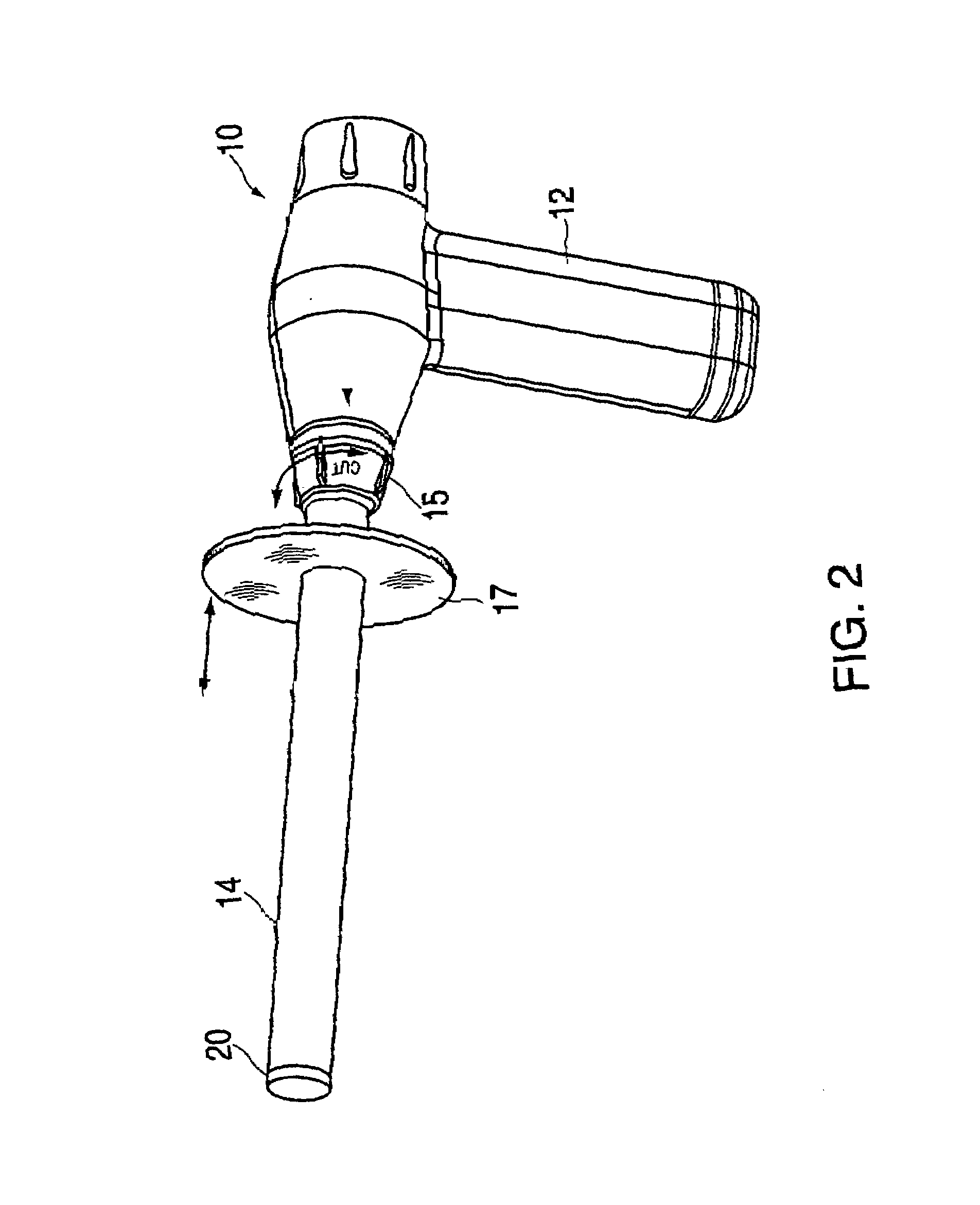
[0019]FIG. 1 of the prior art and FIGS. 2 through 4 according to the present invention illustrate differing embodiments of a mechanical tissue morcellator 10 to generally include a handle 12, a blade sheath 14, a drive tube 18, and a rotary cutting blade 20. Additionally, a barrel 16 and a trigger 22 may generally be included.

[0020]The handle 12, which is preferably formed in two mating halves of polycarbonate or ABS plastic, provides a front aperture 24 through which the blade sheath 14, barrel 16, and drive tube 18 extend. The blade sheath 14 is rigidly mounted to the handle to prevent the sheath from rotating with the drive tube 18 and / or the barrel 16. In one embodiment of the construction, the barrel 16 surrounds the drive tube 18 and extends outwardly therewith from the handle 12 to the cutting blade 20. In an alternative embodiment, the drive tube 18 surrounds the barrel 16 and extends outwardly therewith from the handle to the cutting blade 20.

[0021]At the front aperture 24,...


PUM


Abstract

An improvement to a tissue removal device, that is, the addition of an adjustable protective guard and/or a retractable protective guard on the blade guard sheath of a mechanical tissue morcellator is presented. The retractable protective guard can be fixedly located at the distal end of a blade guard sheath and can be openly operated by a spring loaded means or a trigger means. The adjustable protective guard is moveably mounted in close contact around the blade sheath and may be positioned at any point along the length of the blade guard sheath in either direction. The addition of the adjustable protective guard and the retractable protective guard on the blade guard sheath of the mechanical tissue morcellator act to control and direct positioning of the tissue morcellator within the body cavity of the patient.

Description

FIELD OF THE INVENTION[0001]The present invention is generally directed to an improvement of a tissue removal device, and more particularly, to the addition of adjustable and / or retractable protective guards on the blade guard of a mechanical tissue morcellator.DESCRIPTION OF THE RELATED ART[0002]The process of minimally invasive surgery has been augmented by specialized tools for decades. In recent years, however, special medical equipment and / or electronic tools have been developed to aid surgeons. For example, special surgical instruments handled via tubes inserted into the body through small openings, fiber optic cables, and miniature video cameras to name a few. This equipment has allowed for features and advantages such as: visual magnification—use of a large viewing screen improves visibility; stabilization—electromechanical damping of vibrations, due to machinery or shaky human hands; and reduced number of incisions needed to perform the surgery.[0003]In modern surgery acces...

Claims


Application Information

Patent Timeline
Patent Type & Authority Applications(United States)
IPC IPC(8): A61B17/32
CPCA61B17/32053A61B17/320758A61B2019/306A61B2017/3484A61B2017/3492A61B2017/320775A61B2090/036
Inventor VOSOUGH, KHASHAYAR
Owner VOSOUGH KHASHAYAR
Why Eureka
Try Eureka