Subterranean deposits of
coal contain substantial quantities of entrained
methane gas limited in production in use of
methane gas from
coal deposits has occurred for many years.
Substantial obstacles, however, have frustrated more extensive development and use of
methane gas deposits in
coal seams.
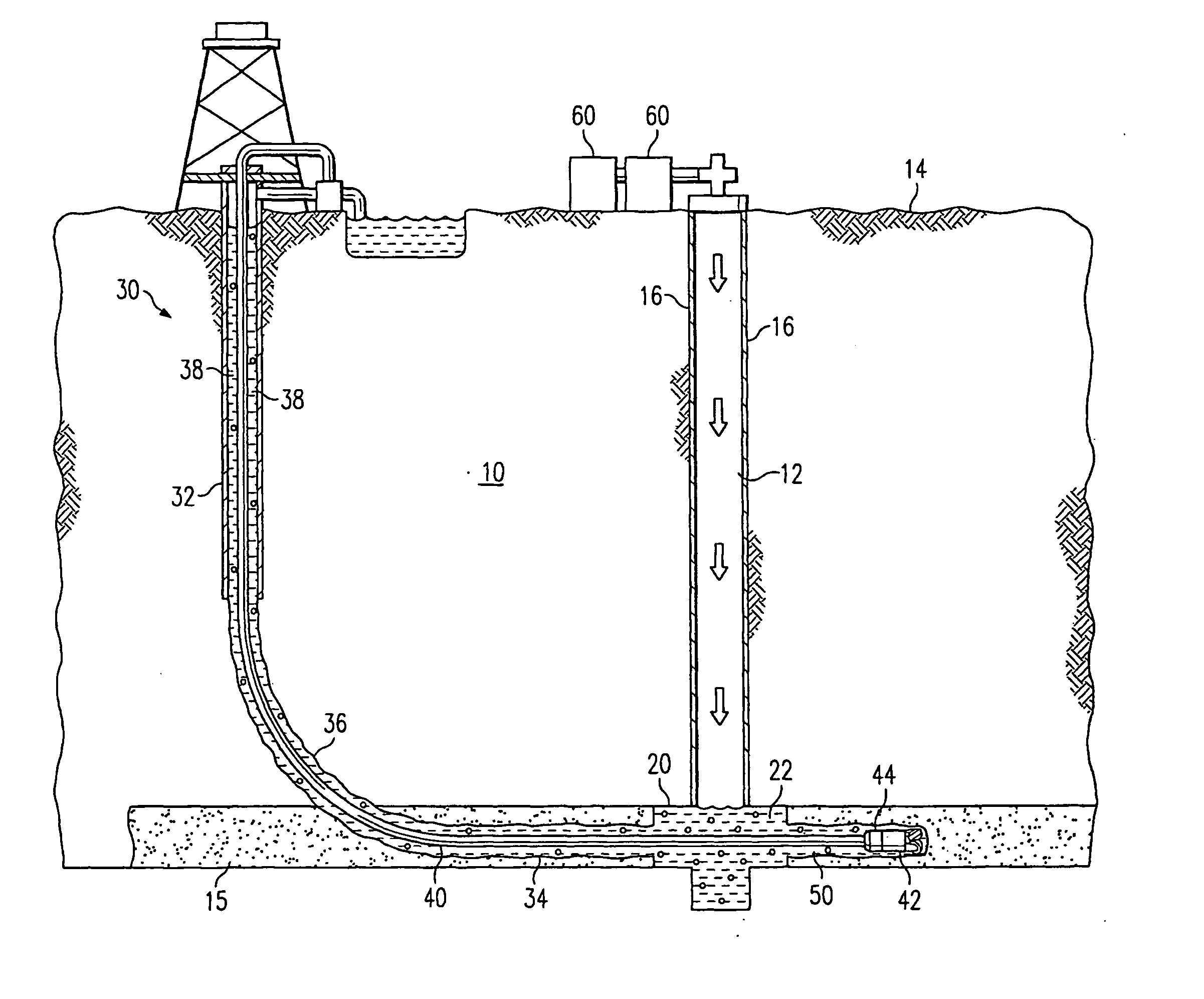
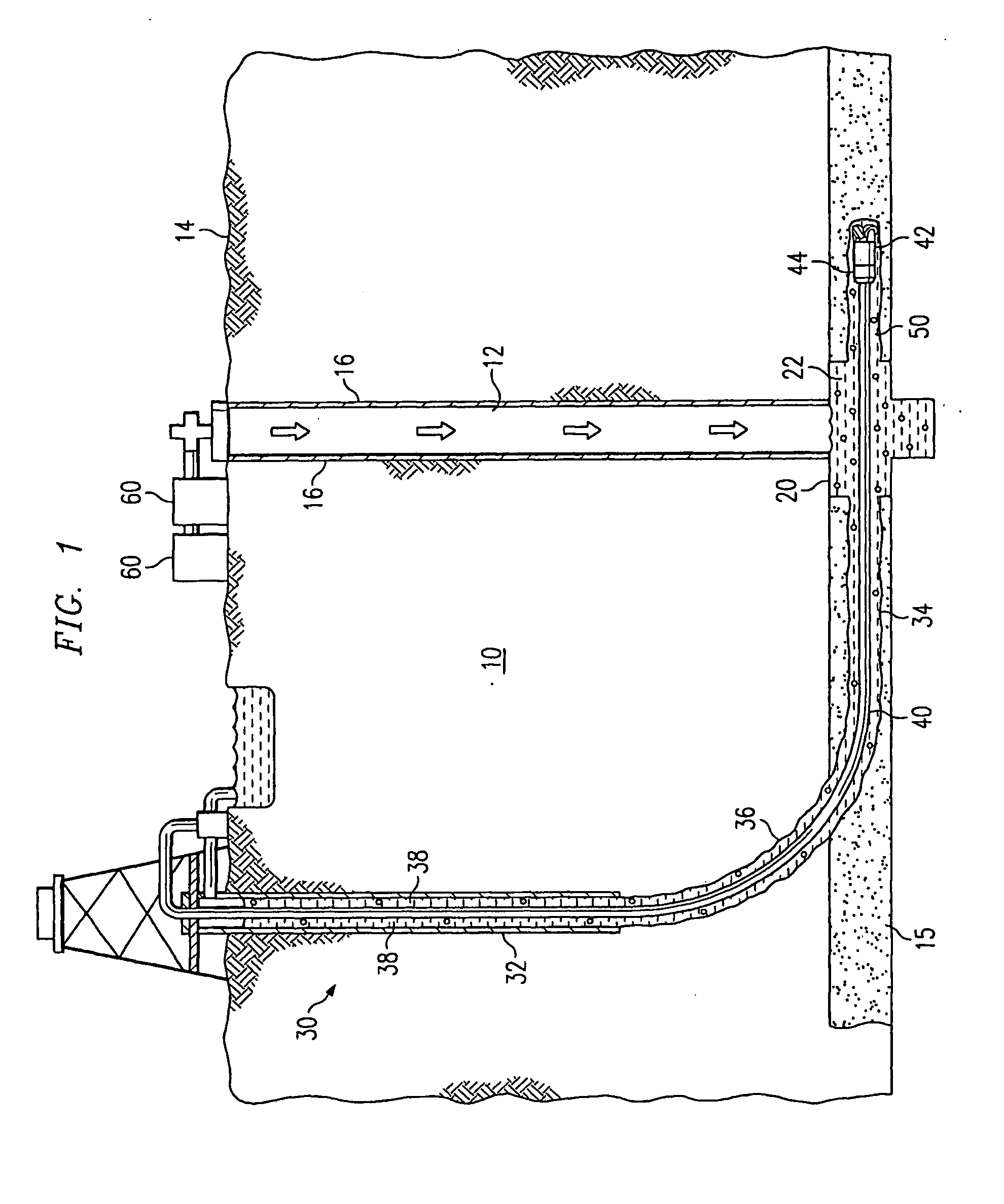
The foremost problem in producing
methane gas from coal seams is that while coal seams may extend over large areas of up to several thousand acres, the coal seams are fairly shallow in depth, varying from a few inches to several meters.
Thus, while the coal seams are often relatively near the surface, vertical wells drilled into the coal deposits for obtaining
methane gas can only drain a fairly small
radius around the coal deposits.
Further, coal deposits are not amendable to pressure fracturing and other methods often used for increasing
methane gas production from rock formations.
As a result, once the gas easily drained from a vertical well bore in a coal seam is produced, further production is limited in volume.
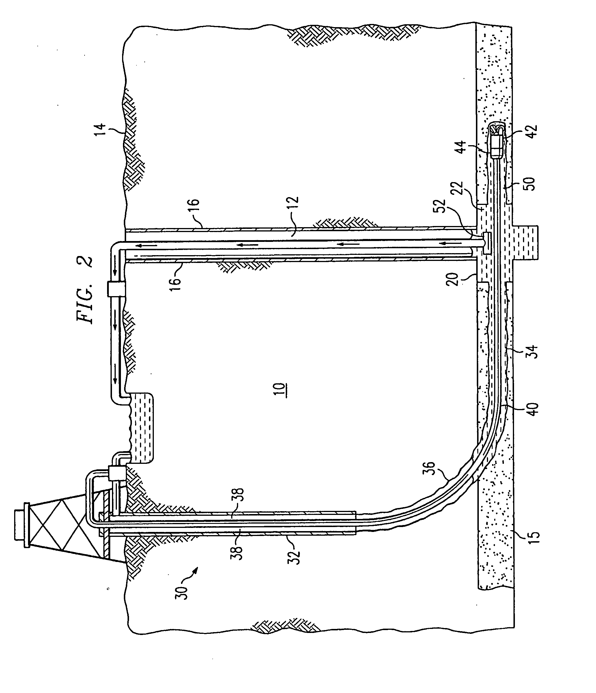
Such horizontal drilling techniques, however, require the use of a radiused well bore which presents difficulties in removing the entrained water from the coal seam.
The most efficient method for pumping water from a subterranean well, a
sucker rod pump, does not work well in horizontal or radiused bores.
A further problem for surface production of gas from coal seams is the difficulty presented by under balanced drilling conditions caused by the porousness of the coal seam.
This results in entrainment of drilling finds in the formation, which tends to plug the pores, cracks, and fractures that are needed to produce the gas.
While the use of subterranean methods allows water to be easily removed from a coal seam and eliminates under balanced drilling conditions, they can only access a limited amount of the coal seams exposed by current mining operations.
The limitations of underground rigs limits the reach of such horizontal holes and thus the area that can be effectively drained.
As a result, many horizontal bores must be drilled to remove the gas in a limited period of time.
Furthermore, in conditions of high gas content or migration of gas through a coal seam, mining may need to be halted or delayed until a next panel can be adequately degasified.
These production delays add to the expense associated with degasifying a coal seam.
As a result, prior mining systems and drilling technologies generally cannot be used in Appalachia or other hilly terrains.
Thus, less effective methods must be used, leading to production delays that add to the expense associated with degasifying a coal seam.
These by-products are typically disposed of by simply pouring them at the surfaces or, if required by environmental regulations, hauling them off-site at great expense.
While the use of subterranean methods allows water to be easily removed from a coal seam and eliminates under-balanced drilling conditions, they can only access a limited amount of the coal seams exposed by current mining operations.
The limitations of underground rigs limits the reach of such horizontal holes and thus the area that can be effectively drained.
In addition, the
degasification of a next panel during mining of a current panel limits the time for degasification.
As a result, many horizontal bores must be drilled to remove the gas in a limited period of time.
Furthermore, in conditions of high gas content or migration of gas through a coal seam, mining may need to be halted or delayed until a next panel can be adequately degasified.
These production delays add to the expense associated with degasifying a coal seam.
An equipment failure occurring during high speed rotation of the above-described underreamer may cause serious harm to operators of the underreamer as well as damage and / or destruction of additional drilling equipment.
The varied positions of the
cutting blades relative to the
drill pipe may cause an out-of-balance condition of the underreamer, thereby creating undesired vibration and rotational characteristics during cavity formation, as well as an increased likelihood of equipment failure.
A common problem in producing methane gas from coal seams may be vertical separation of multiple thin
layers of coal within a coal seam.
Further, coal deposits are not amenable to pressure fracturing and other methods often used for increasing gas production from conventional rock formations.
As a result, production of gas may be limited in volume.
One problem in producing methane gas from coal seams is that while coal seams may extend over large areas, up to several thousand acres, and may vary in depth from a few inches to many feet.
Thus, vertical wells drilled into the coal deposits for obtaining methane gas can generally only drain a fairly small
radius of methane gas in low and even medium permeability coal deposits.
As a result, once gas in the vicinity of a vertical well bore is produced, further production from the coal seam through the vertical well is limited.
Another problem in producing methane gas from coal seams is subterranean water which must be drained from the coal seam in order to produce the methane.
This recharge of the coal seam extends the time required to drain the coal seam and thus prolongs the production time for entrained methane gas which may take five years, ten years, or even longer.
One problem of production of gas from coal seams may be the difficulty presented at times by over-balanced drilling conditions caused by low
reservoir pressure and aggravated by the
porosity of the coal seam.
The
drilling fluid exerts a
hydrostatic pressure on the formation which, when exceeding the pressure of the formation, can result in a loss of drilling fluid into the formation.
This results in entrainment of drilling finds in the formation, which tends to plug the pores, cracks, and fractures that are needed to produce the gas.
Using a gas such as
nitrogen in the drilling fluid reduces the hydrostatic pressure, but other problems can occur as well, including increased difficulty in maintaining a desired pressure condition in the well
system during
drill string
tripping and connecting operations.
When removing such liquid, entrained coal fines and other fluids from the subterranean zone through pumping, methane gas may enter the pump inlet which reduces pump efficiency.
One problem of surface production of gas from coal seams may be the difficulty presented at times by over-balanced drilling conditions caused by the
porosity of the coal seam.
The drilling fluid exerts a hydrostatic pressure on the formation which, if it exceeds the pressure of the formation, can result in a loss of drilling fluid into the formation.
This results in entrainment of drilling finds in the formation, which tends to plug the pores, cracks, and fractures that are needed to produce the gas.
Other problems include a difficulty in maintaining a desired pressure condition in the well
system during
drill string
tripping and connecting operations.

