

Fireproof bulkhead of a highly porous structure with intumescent coating and method for its production
a high-porous structure and intumescent coating technology, applied in coatings, building repairs, transportation and packaging, etc., can solve the problems of no resistance, no appreciable resistance, high-porous structure, etc., and achieve the effect of low weight and high air permeability
- Summary
- Abstract
- Description
- Claims
- Application Information
AI Technical Summary
Benefits of technology
Problems solved by technology
Method used
Image

Examples
example 1
[0043] On a very open-cell, reticulated foam of aluminum, a low-viscosity, hydrolysis-resistant, intumescent lacquer is applied, for example by spraying. After drying of the intumescent coating, the foam can be used as a fireproof bulkhead. During the intumescence of the coating into a thermal foam, the intumescent coating is anchored in the foam microstructure and completely closes the spaces lying between the cell walls.
[0044] According to the above example, a fireproof bulkhead according to the invention can likewise be produced by the open-cell foam of aluminum being replaced by an open-cell foam of slip-treated aluminum with a ceramic coating.
example 2
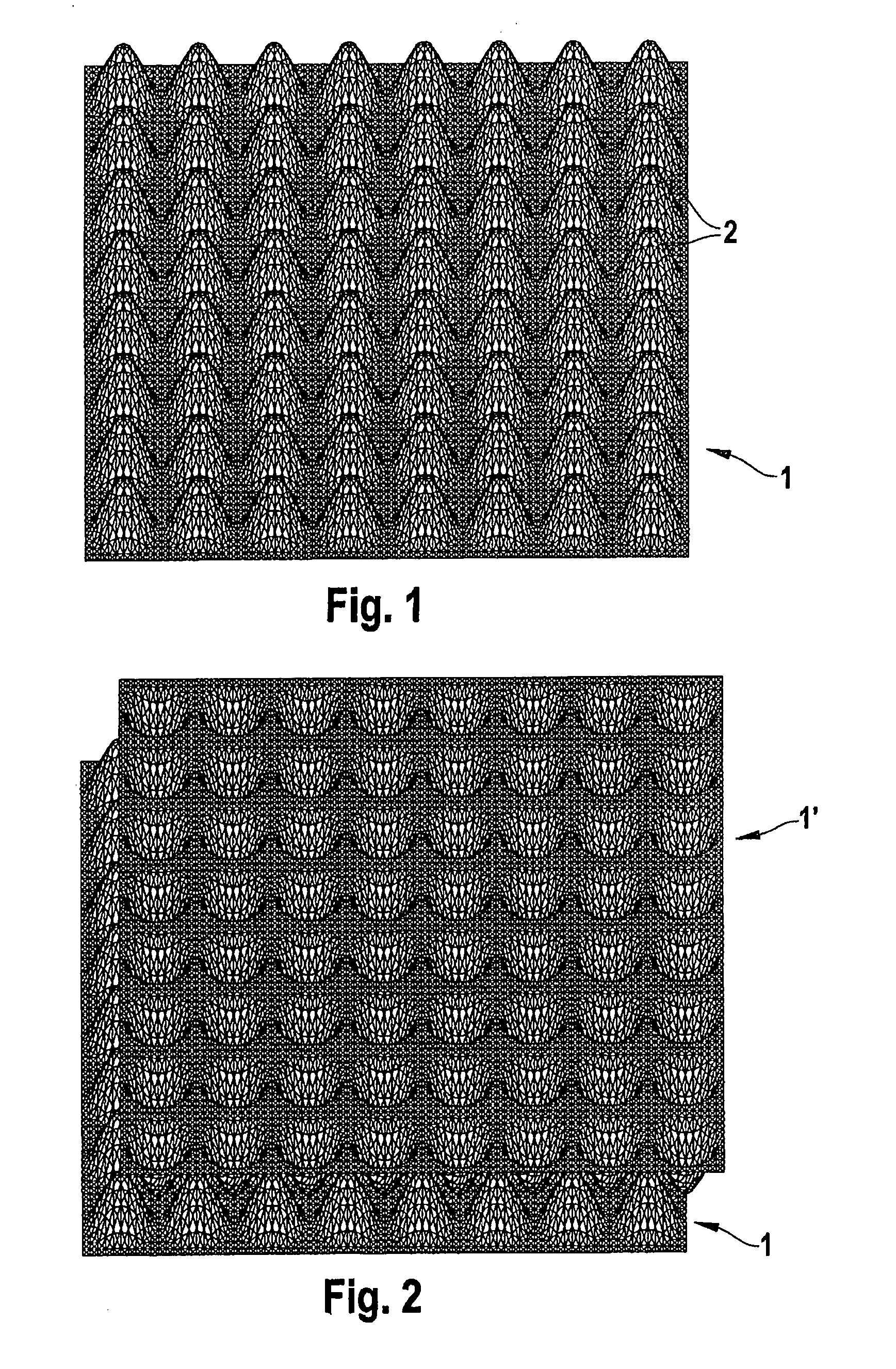
[0045] An open-cell knitted fabric of a partially stretched polyester is thermoformed at elevated temperature to form a nub structure. After impregnating with a reactive resin, this reactive resin is cured at elevated temperature. FIG. 1 shows a nub structure 1 produced in such a way. Regularly arranged nubs are formed in the nub structure 1. The nub structure 1 is coated with an intumescent coating for example by immersion in a low-viscosity, hydrolysis-resistant, intumescent coating solution. After drying of the coating, the coated nub structure can be used as a fireproof bulkhead.
[0046]FIG. 2 shows two interlaced nub structures 1, 1′ as they have been produced in accordance with the above example. After coating with a reactive resin, the nub structures 1 and 1′ are interlaced inversely with one another. The nubs of the nub structure 1′ thereby engage in the cavities that lie between the nubs of the nub structure 1. In this arrangement, the nubs of the two structures touch one an...
PUM
| Property | Measurement | Unit |
|---|---|---|
| Temperature | aaaaa | aaaaa |
| Temperature | aaaaa | aaaaa |
| Temperature | aaaaa | aaaaa |
Abstract
Description
Claims
Application Information