

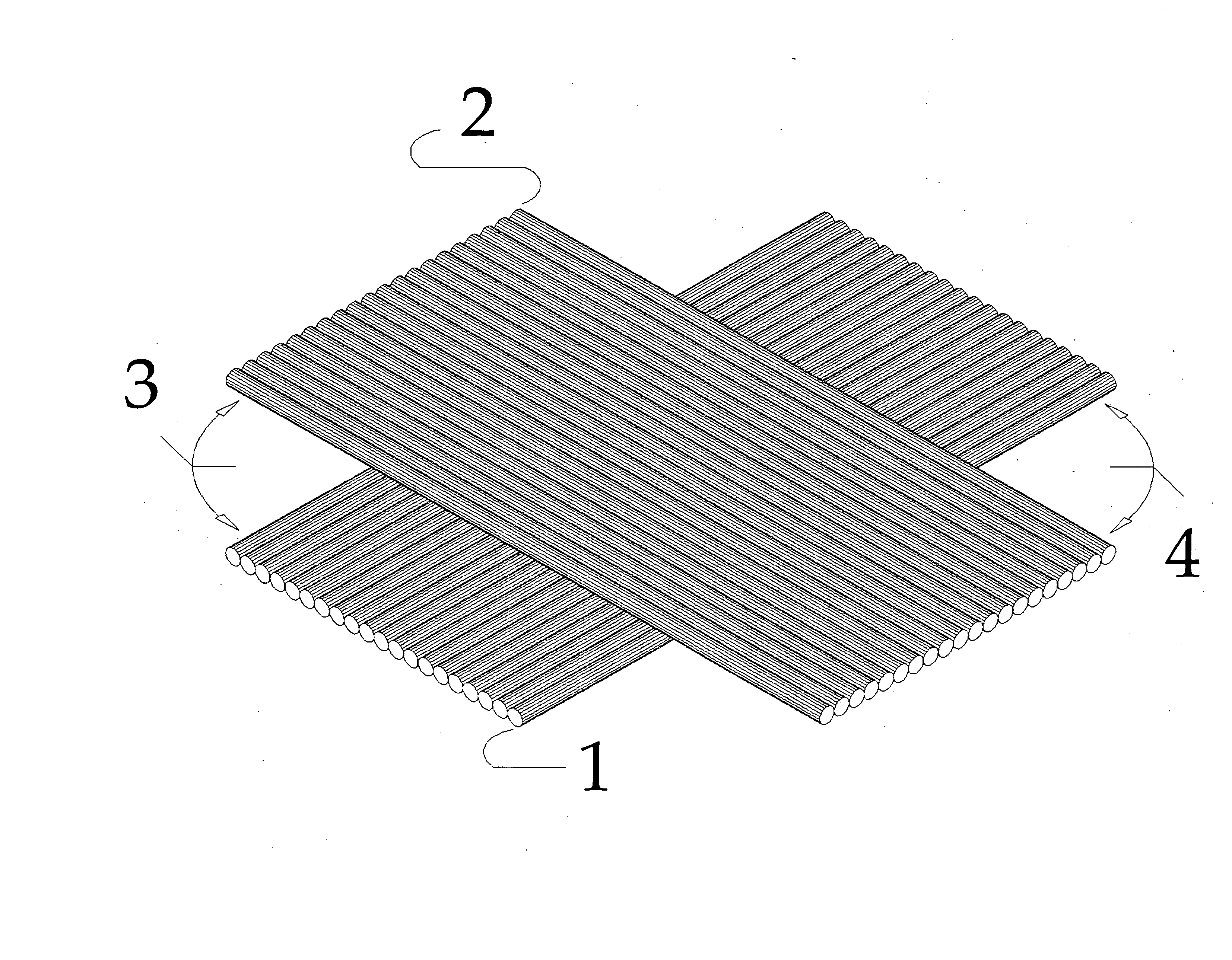
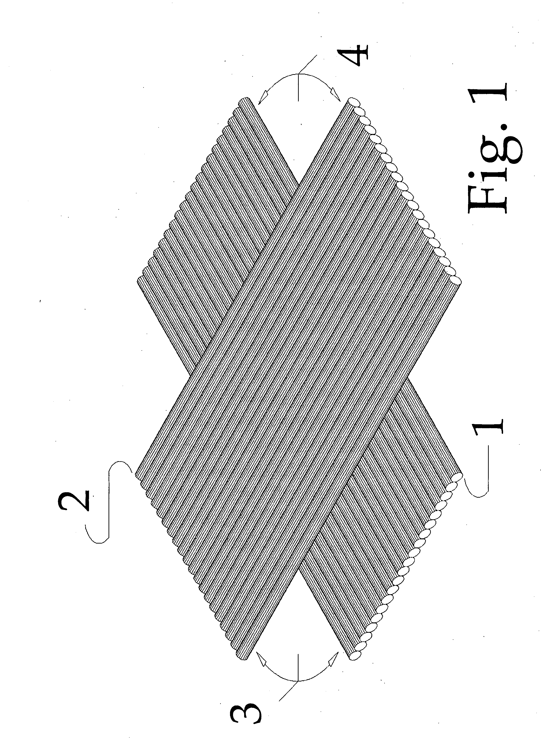
Multi-Layered, Variable-angled, Non-Crimped Fabric for Reinforcement of Composite Materials
a composite material and fabric technology, applied in the field of textiles, can solve the problems of 0 degree/90 degree/+45 degree/45 degree yarn falling apart, weak spots created by weaves,
- Summary
- Abstract
- Description
- Claims
- Application Information
AI Technical Summary
Benefits of technology
Problems solved by technology
Method used
Image

Examples
example
[0032] An example of a polymer and liquid bath is Eastman's WD-30 polyester. Polyester solids at a wt. percent level of 30% are suspended in water to form the polymer / liquid bath. These polyester solids are compatible with polyester resins and dissolve therein in the practice of the present invention. Other polymers which may be useful include, but are not limited to, epoxy polymer / liquid baths and epoxy resins, and phenolic polymer / liquid baths and phenolic resins.
[0033] Two types of fabric were manufactured on a pilot machine of van Wees: Tilburg, The Netherlands. The main characteristic of the pilot machine is that it has a 1,700 mm wide by 541 mm diameter heated drum. The yarns were drawn from a creel, through a reed, through an impregnation roller(the polymer bath) for a adding a binder, and onto a heated Teflon-coated drum that was wrapped with the carrier. The yarns advanced by pitch (depending on the width of the yarn) as the yarns complete one revolution around the drum, a...
PUM
| Property | Measurement | Unit |
|---|---|---|
| angle | aaaaa | aaaaa |
| angle | aaaaa | aaaaa |
| angle | aaaaa | aaaaa |
Abstract
Description
Claims
Application Information