Al technical title is built by PatSnap Al team. It summarizes the technical point description of the patent document.
a technology for monitoring structures and structures, applied in the direction of vehicle headlamps, tyre tread bands/patterns, vehicle registration/indication of working, etc., can solve problems such as subject to wear and tear, and achieve the effect of increasing the service life of the system
Inactive Publication Date: 2008-03-13
INTELLIGENT TECH INT
View PDF18 Cites 64 Cited by
Summary
Abstract
Description
Claims
Application Information
AI Technical Summary
This helps you quickly interpret patents by identifying the three key elements:
Problems solved by technology
Method used
Benefits of technology
[0018] Transmission of the signal may be performed via satellite and / or the Internet to the remote monitoring facility which can receive the analysis, which would typically relate to the structural integrity of the structure such as excessive wear and tear or excessive vibration, and then schedule maintenance or repair of part or all of the structure dependent on the extent and nature of the condition of the structure. The monitoring facility would receive the identification or location of the structure to know where maintenance is required and also the location of the sensor reporting the condition which give rises to the need for maintenance and thus can, for example, accurately direct the personnel to the damaged area of the structure.
[0020] The time or interval at which the sensors obtain data may be regulated. This regulation may entail requiring detection of the presence of a predetermined condition which requires monitoring of the structure since it may be a symptom of damage to the structure. Thus, only when one of a predetermined number of such conditions is detected, are the sensors directed to obtain data. This increase the service life of the system. nevertheless, it is also possible to command the sensors to obtain data upon reception of a signal from the monitoring facility.
[0022] To increase the service life of the system, a wake-up sensor may be coupled to the sensors for detecting one of a predetermined number of conditions which require monitoring of the structure and only when one of the predetermined number of conditions is detected would the wake-up sensor direct the sensors to obtain data.
Problems solved by technology
Bridges and other infrastructure are used daily and subject to wear and tear.
Method used
Image
Click on the blue label to locate the original text in one second.
Reading with bidirectional positioning of images and text.
Examples
Embodiment Construction
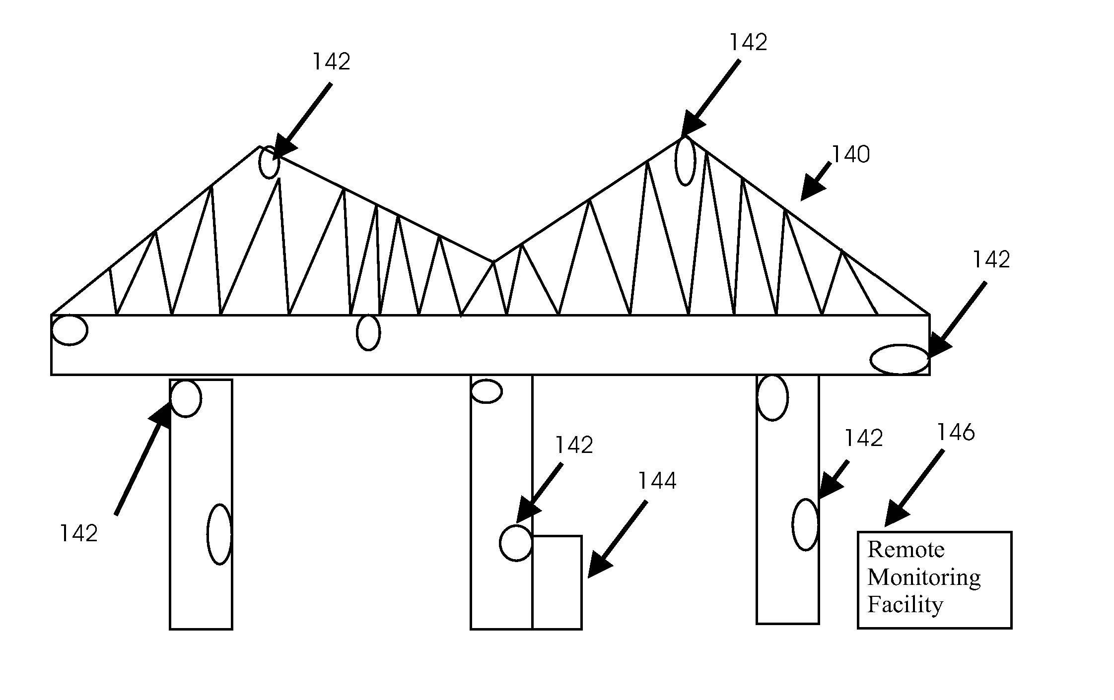
[0062] Although many of the examples below relate to a cargo space in an asset, the invention is not limited to any particular space in any particular asset and is thus applicable to all types of assets including vehicles, shipping containers and truck trailers and to all spaces or compartments of a vehicle including, for example, the passenger compartment and the trunk of an automobile or truck.
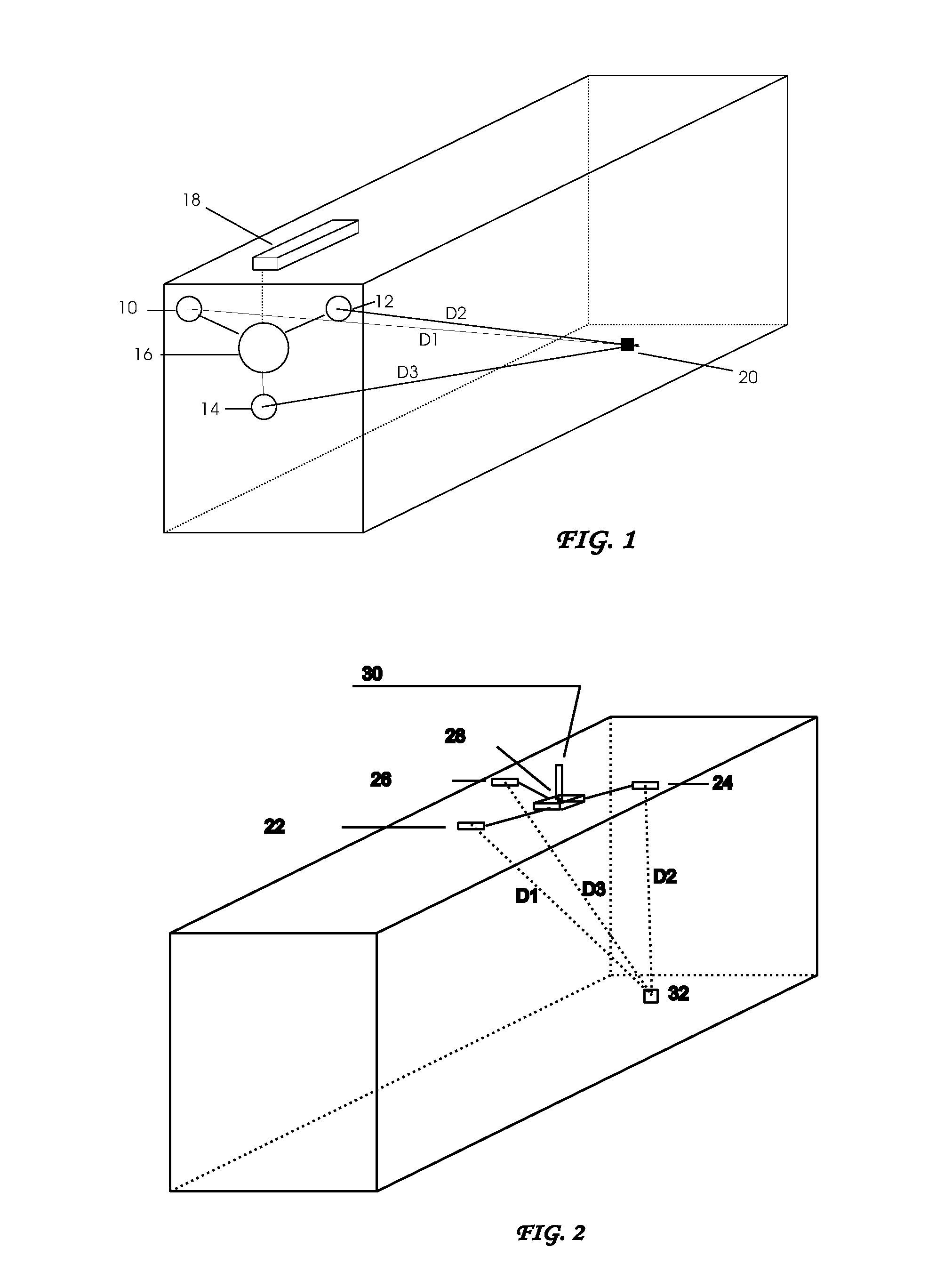
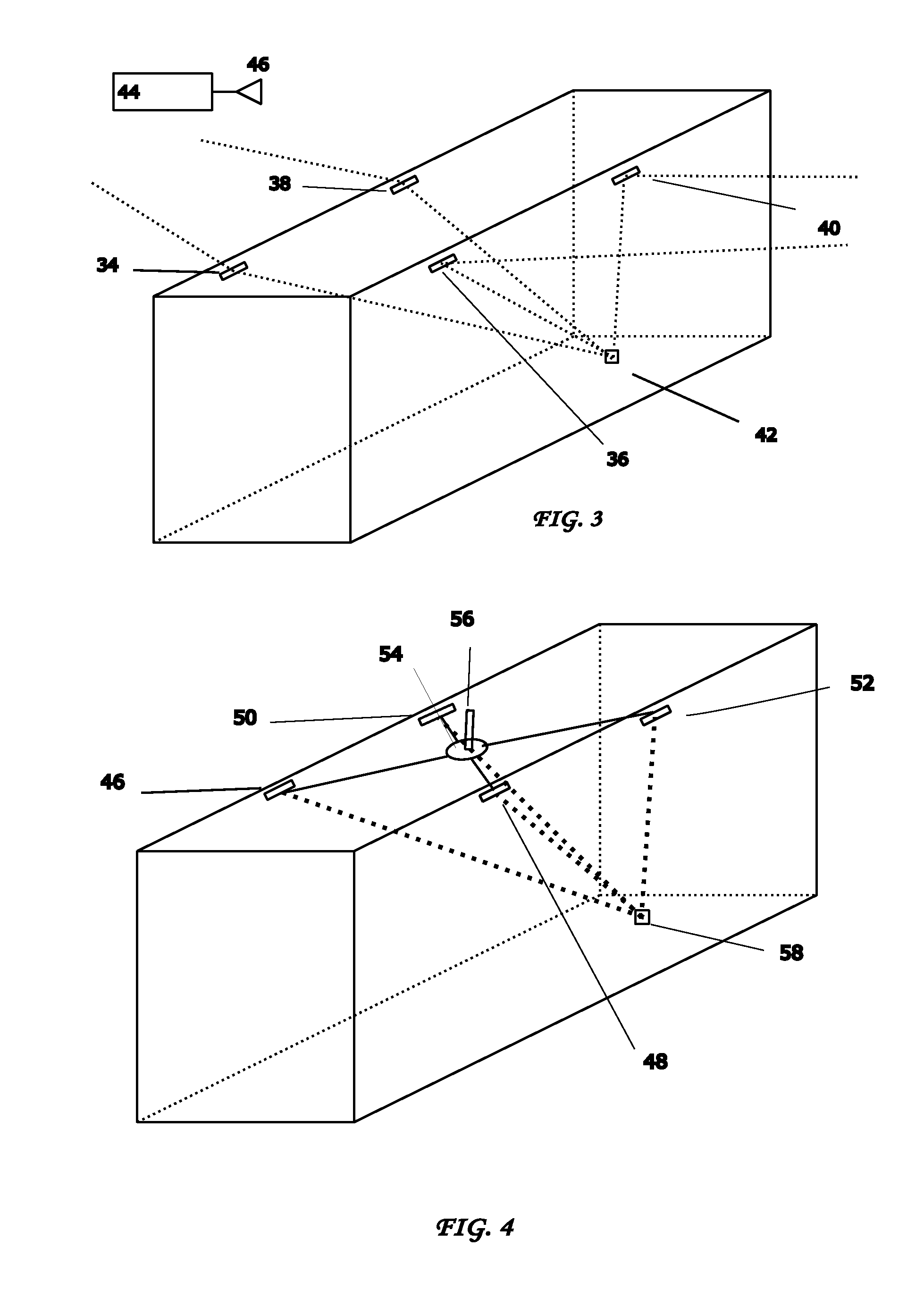
[0063] Referring to the accompanying drawings, FIGS. 1-10 illustrate a method and system for identifying and locating an RFID-tagged article inside a cargo space defined by a frame. The RFID tags can be active, passive or a combination of both, or MIR transmitters, or devices providing backscatter. The system can employ multiple antennas inside a cargo space, truck trailer or other vehicle cargo space as illustrated in FIGS. 1-6. The system is preferably designed for a low power battery operation when the cargo space is not tethered to a power source. Some energy harvesting methods for powe...
PUM
Abstract
Method and system for monitoring structures such as bridges includes arranging sensors on the structure, obtaining data via the sensors, analyzing the data to determine the presence of a non-optimal condition relating to the integrity of the structure and transmitting the data or a signal indicative of the analysis with an identification or location of the sensors and the structure to a remote monitoring facility. Transmission of the signal may be performed via satellite and / or the Internet to the monitoring facility which can schedule maintenance or repair of the structure. The monitoring facility would receive the identification or location of the structure to know where maintenance is required and the location of the sensor(s) reporting the condition which give rises to the need for maintenance and thus can accurately direct the personnel to the damaged area of the structure.
Description
CROSS REFERENCE TO RELATED APPLICATIONS [0001] This application is: [0002] 1. a continuation-in-part (CIP) of U.S. patent application Ser. No. 10 / 940,881 filed Sep. 13, 2004 which is: [0003] A. a CIP of U.S. patent application Ser. No. 10 / 457,238 filed Jun. 9, 2003, now U.S. Pat. No. 6,919,803 which claims priority under 35 U.S.C. §119(e) of U.S. provisional patent application Ser. No. 60 / 387,792 filed Jun. 11, 2002; [0004] B. a CIP of U.S. patent application Ser. No. 10 / 931,288 filed Aug. 31, 2004, now U.S. Pat. No. 7,164,117; [0005] 2. a CIP of U.S. patent application Ser. No. 11 / 278,979 filed Apr. 7, 2006 which is a CIP of U.S. patent application Ser. No. 10 / 931,288 filed Aug. 31, 2004, now U.S. Pat. No. 7,164,117; [0006] 3. a CIP of U.S. patent application Ser. No. 11 / 380,574 filed Apr. 27, 2006 which is a CIP of U.S. patent application Ser. No. 10 / 931,288 filed Aug. 31, 2004, now U.S. Pat. No. 7,164,117; [0007] 4. a CIP of U.S. patent application Ser. No. 11 / 420,497 filed May 2...
Claims
Application Information
Patent Timeline
Application Date:The date an application was filed.
Publication Date:The date a patent or application was officially published.
First Publication Date:The earliest publication date of a patent with the same application number.
Issue Date:Publication date of the patent grant document.
PCT Entry Date:The Entry date of PCT National Phase.
Estimated Expiry Date:The statutory expiry date of a patent right according to the Patent Law, and it is the longest term of protection that the patent right can achieve without the termination of the patent right due to other reasons(Term extension factor has been taken into account ).
Invalid Date:Actual expiry date is based on effective date or publication date of legal transaction data of invalid patent.
Patent Type & Authority Applications(United States)