Liquid ejecting head and liquid ejecting apparatus

Active Publication Date: 2008-03-13
SEIKO EPSON CORP
View PDF2 Cites 8 Cited by
  • Summary
  • Abstract
  • Description
  • Claims
  • Application Information

AI Technical Summary

Benefits of technology

[0014]In the configuration of a liquid ejecting head according to the invention described above, it is preferable that each of the separate flow channels includes a liquid supply passage that is in communication with the pressure generation chamber and is configured to have a relatively small sectional area (i.e., cross section) along a width direction thereof in comparison with that of the pressure generation chamber, and said each of the separate flow channels further includes a communication passage through (i.e., via) which the liquid supply passage is in communication with the communication portion, the communication passage being configured to have a relatively large sectional area along a width direction thereof in comparison with that of the liquid supply passage. Such a configuration offers, advantageously, more smooth flow of liquid at the boundary between the communication porti

Problems solved by technology

With such a configuration, piezoelectric elements are “voltage-deflected” to cause the deformation of a diaphragm, which results in expansion/contraction of the inner capacity of the pressure generation chambers.
In the configuration of related art, there is a problem in that “air bubble entrainment (drift of air bubbles)” could occur at the boundaries between the communicating portion and separate flow channels, each of which is demarcated by

Method used


Image

  • Liquid ejecting head and liquid ejecting apparatus
  • Liquid ejecting head and liquid ejecting apparatus
  • Liquid ejecting head and liquid ejecting apparatus

Examples


Embodiment Construction

[0023]With reference to the accompanying drawings, exemplary embodiments of the present invention are described in detail below.

Exemplary Embodiment

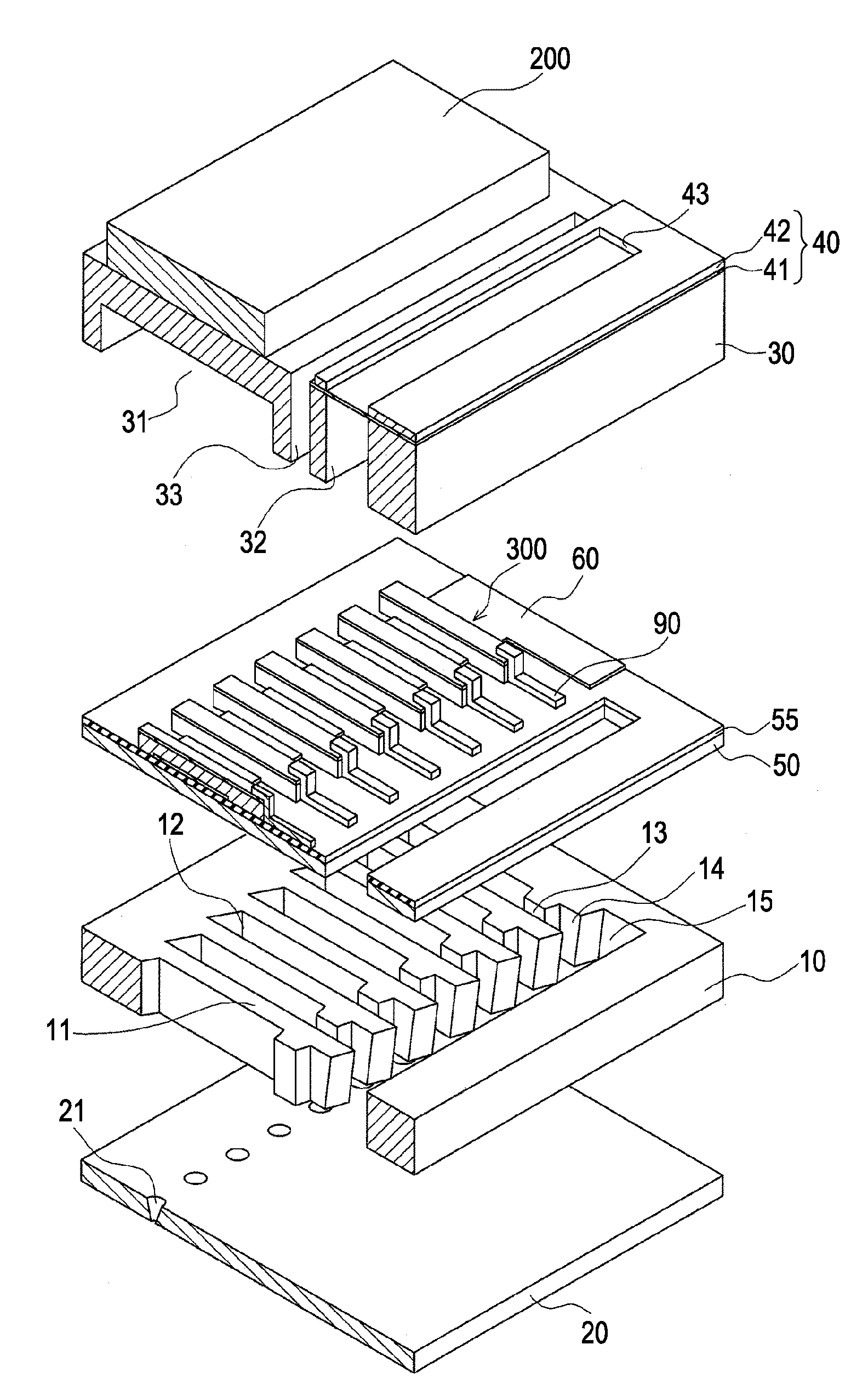
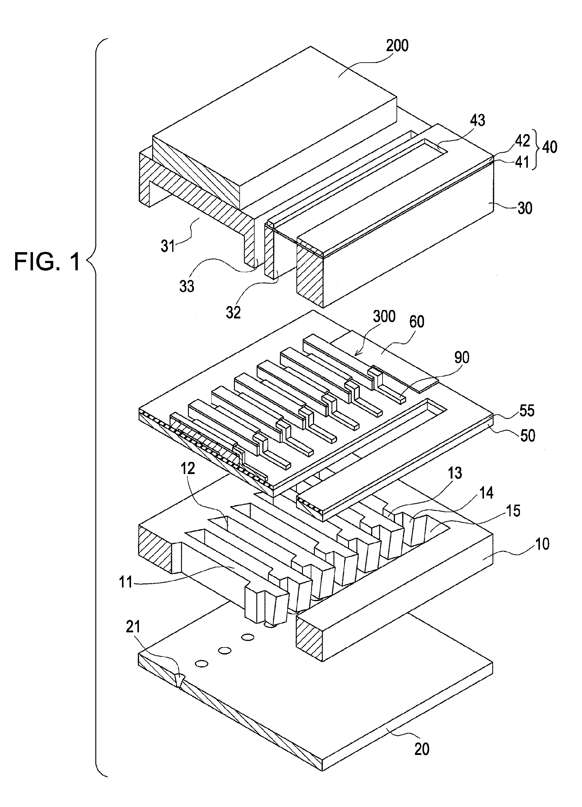
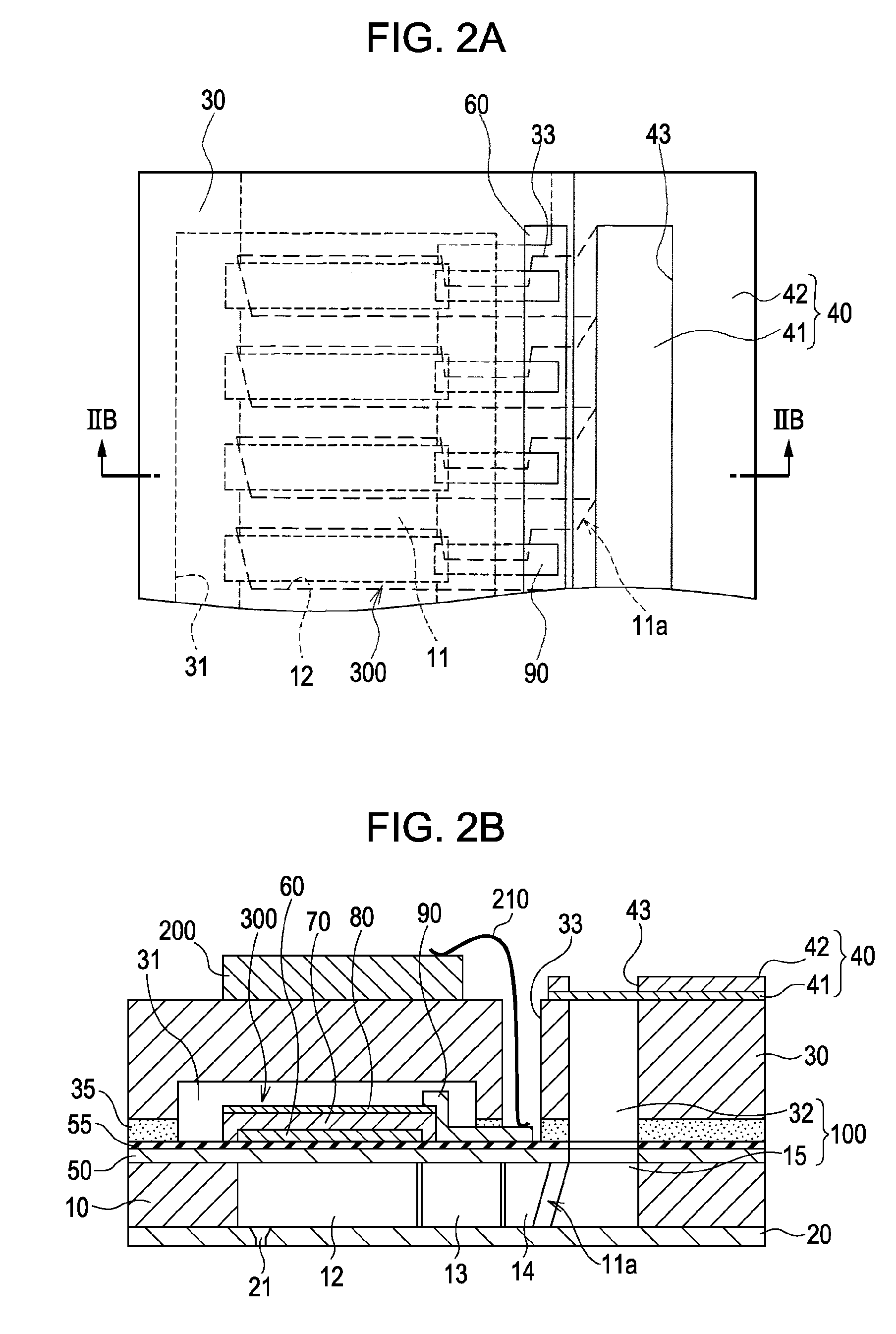
[0024]FIG. 1 is an exploded perspective view of the overall configuration of an ink-jet recording head, which is illustrated herein as an example of a liquid ejecting head according to the present embodiment of the invention. FIG. 2A is a plane view of the ink-jet recording head illustrated in FIG. 1, whereas FIG. 2B is a sectional view taken along the line IIB-IIB thereof. FIG. 3 is a perspective view that schematically illustrates an example of the tip portions of partition walls. FIG. 4A is an enlarged plane view of the tip portions of partition walls, whereas FIGS. 4B and 4C are enlarged sectional views thereof.

[0025]In this embodiment of the invention, a fluid channel formation substrate 10 is made of a silicon single crystal substrate having a crystal face orientation of (110). As illustrated in the drawing, an elastic membrane 50 ...


PUM


Abstract

A liquid ejecting head that includes a fluid channel formation substrate and pressure generation units. The fluid channel formation substrate is made of a silicon single crystal substrate having a crystal face orientation of. The fluid channel formation substrate has a plurality of separate flow channels that include at least pressure generation chambers demarcated by partition walls, each of the pressure generation chambers being in communication with a nozzle opening that ejects liquid drops. The fluid channel formation substrate further has a communication portion that is in communication with each of the separate flow channels. The pressure generation units are provided so as to correspond to the pressure generation chambers and generate a pressure change in the pressure generation chambers so as to cause ejection of liquid drops.

Description

[0001]The entire disclosure of Japanese Patent Application No. 2006-248741, filed Sep. 13, 2006 is expressly incorporated by reference herein.BACKGROUND[0002]1. Technical Field[0003]The present invention relates to a liquid ejecting head that ejects liquid drops from its nozzle openings, and a liquid ejecting apparatus that is provided with such a liquid ejecting head. More particularly, the present invention relates to an ink-jet recording head that ejects ink drops as one specific example of various kinds of liquid drops, and an ink-jet recording apparatus that is provided with such an ink-jet recording head.[0004]2. Related Art[0005]A typical example of various kinds of liquid ejecting heads is an ink-jet recording head, which is used, for example, in a printer, a facsimile machine, and a copying machine. Some of ink-jet recording heads have a fluid channel formation substrate, which has liquid flow channels having pressure generation chambers (i.e., compartments) each of which c...

Claims


Application Information

Patent Timeline
IPC IPC(8): B41J2/05
CPCB41J2/14233B41J2/045B41J2202/11
Inventor MATSUZAWA, AKIRAOTA, MUTSUHIKOTAKAHASHI, TETSUSHIMATSUMOTO, YASUYUKI
Owner SEIKO EPSON CORP
Why Eureka
Try Eureka