Surgical needle and method of manufacturing a surgical needle

a surgical needle and manufacturing method technology, applied in the field of surgical needles, can solve the problems of limited stability of such micro-needles, limited sliding behaviour of needles as they pierce bodies and tissues, etc., and achieve the effects of not easy to manufacture, not easy to produce, and not easy to splin

Active Publication Date: 2008-03-13
AESCULAP AG
View PDF14 Cites 6 Cited by
  • Summary
  • Abstract
  • Description
  • Claims
  • Application Information

AI Technical Summary

Benefits of technology

[0041] In order not to reduce the stability of the needle, it is advantageous if a depth of the indentations relative to the outer surface of the at least one textured-profile lateral face is designed to decrease from a proximal end of the at least one textured-profile lateral-face region in the direction of the needle point. Despite the indentations in the region of the distal end of the needle point being no longer as deep as indentations in the region of the non-tapered needle body, the sliding behaviour of the needle is still markedly improved by the profiling of the needle point itself. In particular, such a profiled needle point may easily be manufactured by electrochemical polishing.
[0042] The textured profile is particularly easy to produce if the plurality of indentations are entirely or partially of a pyramidal design. For example, such a textured profile may be produced by means of a pressure die that has a profile of raised pyramids. In particular, this allows the needle body to be provided with a textured profile that has the shape of a textured profile known from golf balls.
[0043] It would in principle be conceivable to form the needle by injection moulding. It is however particularly advantageous if the plurality of indentations are impressed. This allows a marked improvement of a bending strength of the needle, namely because of the strain hardening of the needle body material that is brought about by the pressing operation.

Problems solved by technology

Because of their dimensions the stability of such micro-needles is limited.
Furthermore, the sliding behaviour of the needle as it pierces body and tissue is limited.

Method used


Image

  • Surgical needle and method of manufacturing a surgical needle
  • Surgical needle and method of manufacturing a surgical needle
  • Surgical needle and method of manufacturing a surgical needle

Examples


Embodiment Construction

[0059] There now follows a description of a preferred embodiment of a surgical needle according to the invention and of a variant of a method according to the invention of manufacturing a surgical needle.

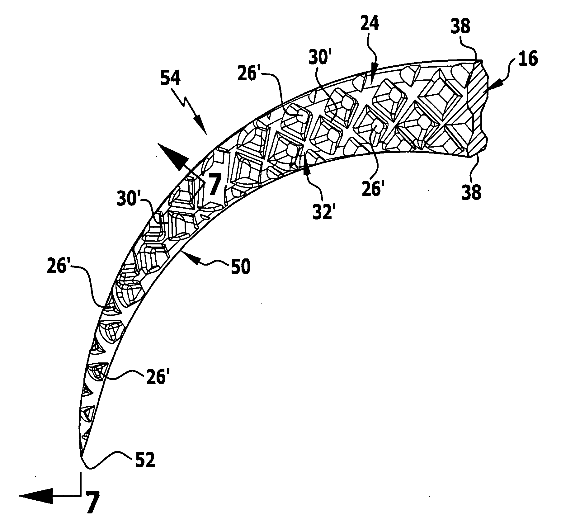
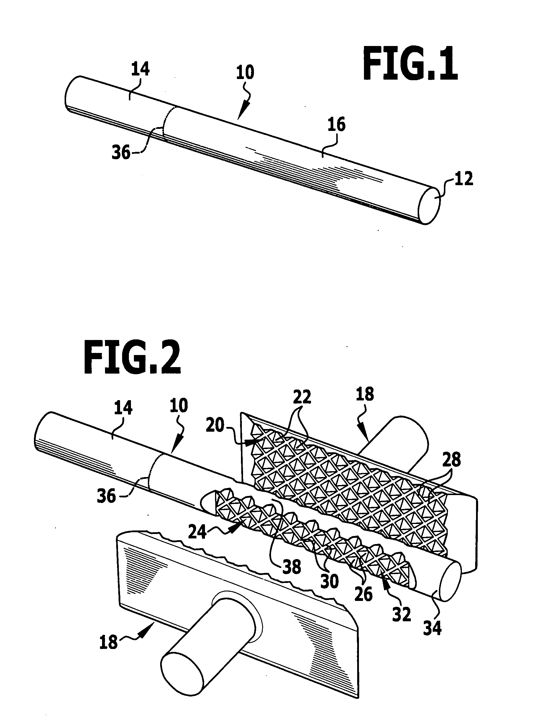
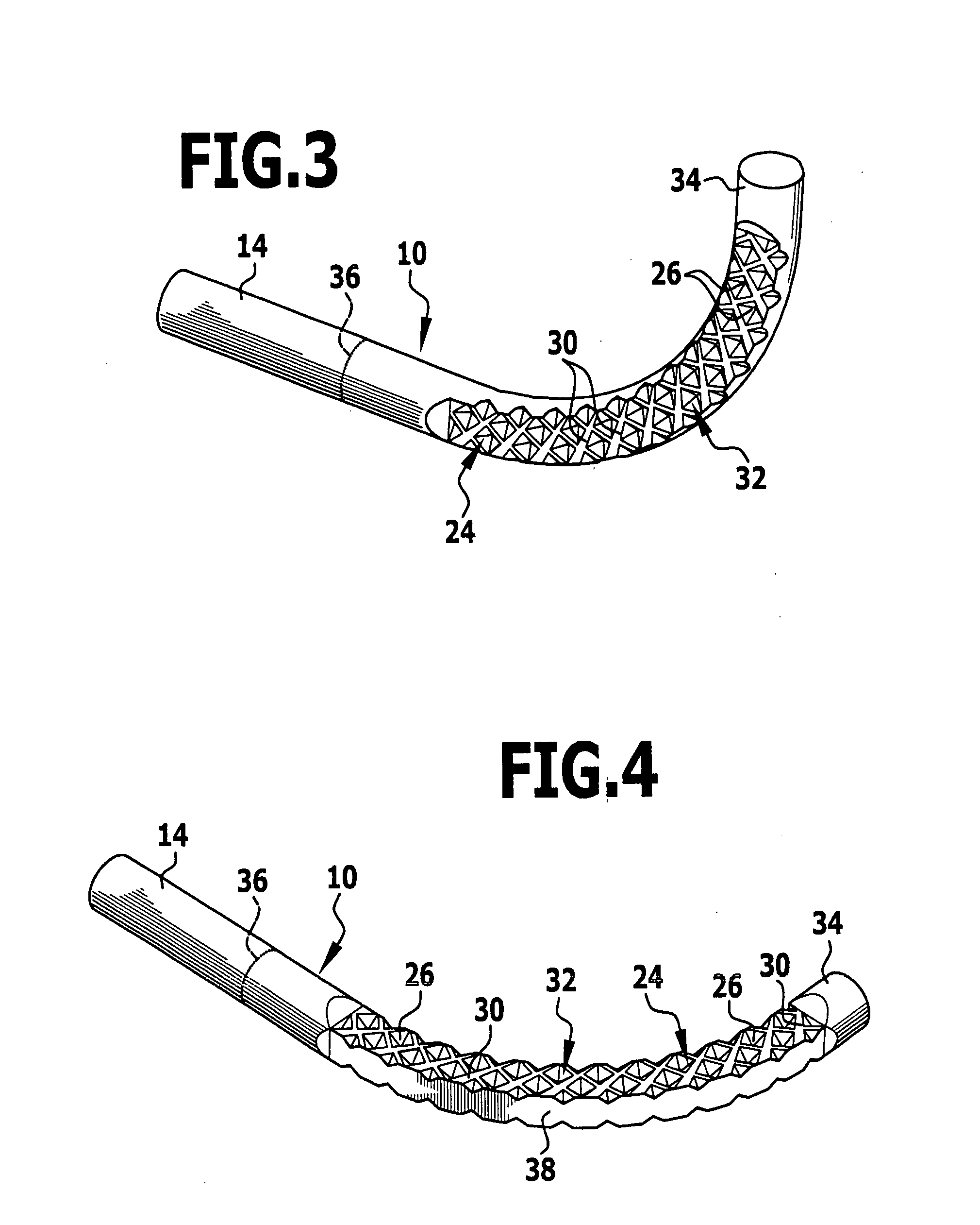
[0060] In the case of the embodiment of a surgical needle 54 that is described in detail with reference to FIGS. 1 to 7 and illustrated at least partially in FIGS. 6 and 7, it relates to a microsurgical needle 54 and a method of manufacturing a surgical needle 54. The starting point of the method is a blank 10 of an elongate cylindrical material, for example a metal wire, which has a circular cross section 12. Approximately one third of the length of the blank 10 serve as auxiliary shank 14, the remaining part of the blank 14 forming a basic body 16 for the surgical needle 54. Manufacture of the surgical needle is however also possible without an auxiliary shank. The blank 10 for manufacturing surgical micro- and macro-needles preferably has a diameter in a range of 0.05 mm to 1.5 ...


PUM

PropertyMeasurementUnit
diameteraaaaaaaaaa
diameteraaaaaaaaaa
widthaaaaaaaaaa

Abstract

In order to develop a surgical needle comprising an elongate needle body and a needle point formed on a distal end of the needle body, wherein the needle body is manufactured in particular from an elongate cylindrical blank, in a way that improves the handling ability of the surgical needle, it is proposed that the needle body has at least one textured-profile lateral face, which comprises at least one textured-profile lateral-face region provided with a textured profile, wherein the textured profile comprises a plurality of indentations and wherein the at least one textured-profile lateral-face region extends as far as the needle point. An improved method of manufacturing a surgical needle is further proposed.

Description

[0001] The present disclosure relates to the subject matter disclosed in German patent application number 10 2006 044 788.3 of Sep. 13, 2006 and German utility model application number 20 2006 014 897.3 of Sep. 18, 2006 which are incorporated herewith by reference and in their entirety. BACKGROUND OF THE INVENTION [0002] The present invention relates to a surgical needle comprising an elongate needle body and a needle point formed on a distal end of the needle body, wherein the needle body is manufactured in particular from an elongate cylindrical blank. [0003] The present invention further relates to a method of manufacturing a surgical needle comprising an elongate needle body and a needle point formed on a distal end of the needle body, wherein the needle body is manufactured in particular from an elongate cylindrical blank. [0004] Surgical needles of the initially described type are used for example in the form of micro-needles during heart surgery. It is known to manufacture mi...

Claims


Application Information

Patent Timeline
Patent Type & Authority Applications(United States)
IPC IPC(8): A61B17/06B21G1/00
CPCA61B17/06066A61B2017/00345B29L2031/7546B29C45/00A61B2017/00433A61B2017/00526A61B2017/00849B21G1/006B22F3/225B22F5/12B22F2003/242B22F2003/245B22F2998/10B22F3/24
Inventor WAESCHLE, TOBIAS
Owner AESCULAP AG
Why Eureka
Try Eureka