Surface-profile measuring instrument

a measuring instrument and surface profile technology, applied in the direction of instruments, mechanical measuring arrangements, manufacturing tools, etc., can solve the problems of deteriorating the resolution of the correction amount by one hundredth of the original, inability to meet the demand for high-speed and high-accuracy, and inability to accelerate by double differentiation of positions. to achieve the effect of improving the efficiency of measuring work

Active Publication Date: 2008-03-13
MITUTOYO CORP
View PDF14 Cites 36 Cited by
  • Summary
  • Abstract
  • Description
  • Claims
  • Application Information

AI Technical Summary

Benefits of technology

[0100]Consequently, the measurement work efficiency can be improved.

Problems solved by technology

Such problems become prominent when a high-speed scanning measurement is conducted by a large-size coordinate measuring instrument for measuring, for instance, a vehicle body.
For instance, if the sampling frequency for detecting the position is decupled, the resolution of the calculated acceleration is degraded to one hundredth of the original, which results in deterioration of the resolution of the correction amount by one hundredth of the original.
Accordingly, the acceleration by double differentiation of the position is not practical and cannot answer to the demand for high-speed and high-accuracy movement
Further, though the acceleration of the measurement slider is obtained by differentiating the position of the measurement slider twice, the acceleration and deformation are generated on a tip end of the spindle 124 or a probe unit during the actual measurement, so that there is naturally a limit on the correction accuracy when focusing on the acceleration of the measurement slider.
Incidentally, though the Document 2 mentions to the provision of the acceleration sensor to obtain the acceleration of the measurement slider, no clear recitation for the performance and providing method are disclosed therein and the provision of acceleration sensor is practically difficult.
However, it is difficult to provide an acceleration sensor capable of detecting 50 μG acceleration for each movement axis (total three acceleration sensors) and, even more, it is impossible to provide acceleration sensors adjacent to the probe unit
As discussed above, since the deformation generated during the scanning measurement cannot be accurately calculated, the deformation cannot be corrected.

Method used


Image

  • Surface-profile measuring instrument
  • Surface-profile measuring instrument
  • Surface-profile measuring instrument

Examples


first embodiment

[0124]A surface-profile measuring instrument according to a first embodiment of the invention will be described below.

[0125]FIG. 20 shows a measurement system (surface-profile measuring instrument) using a scanning probe 130 of the first embodiment

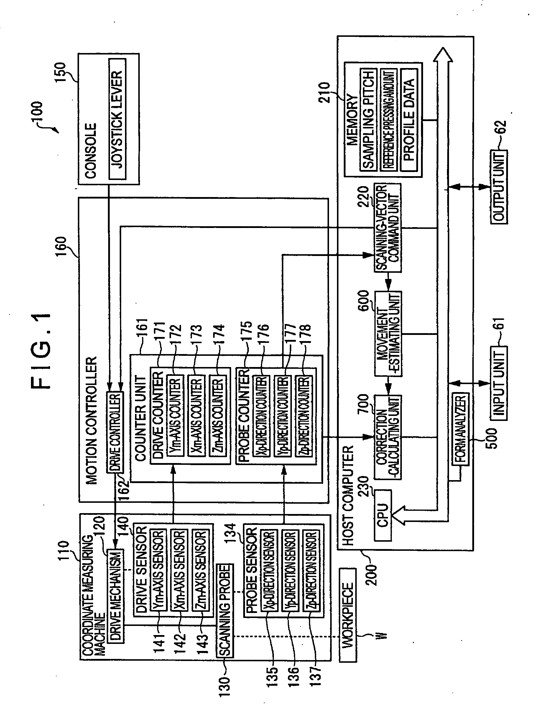
[0126]FIG. 1 is a functional block diagram of the measurement system 100.

[0127]Schematic arrangement of the measurement system 100 is the same as those described in the background section, which includes: a coordinate measuring machine 110; a console 150 for manually operating the movement of the coordinate measuring machine 110; a motion controller 160 for controlling a drive of the coordinate measuring instrument 110; a host computer 200 that send a predetermined command to the motion controller 160 and executes processing such as form analysis of a workpiece W; an input unit 61 for inputting a measurement condition and the like; and an output unit 62 for outputting the measurement result.

[0128]The coordinate measuring machine 110 (see F...

second embodiment

[0320]Next, a second embodiment of the present invention will be described below.

[0321]The basic arrangement of the second embodiment is substantially the same as the above-described first embodiment What is specific about the second embodiment is the provision of an estimation-judging unit 800 that judges the accuracy of the acceleration estimation by comparing an estimated acceleration value calculated by the movement-estimating unit 600 with actual acceleration.

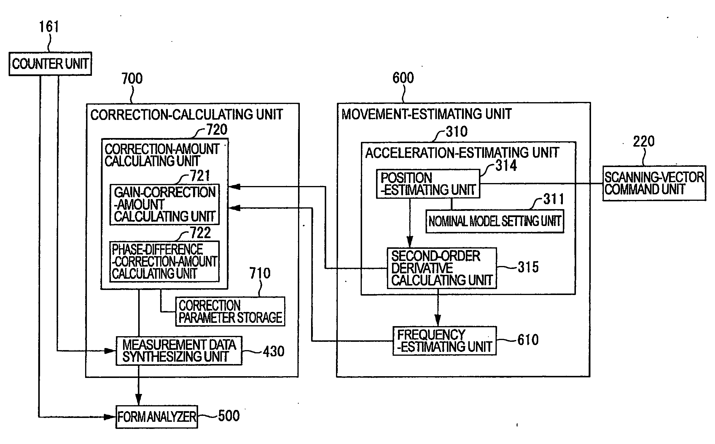
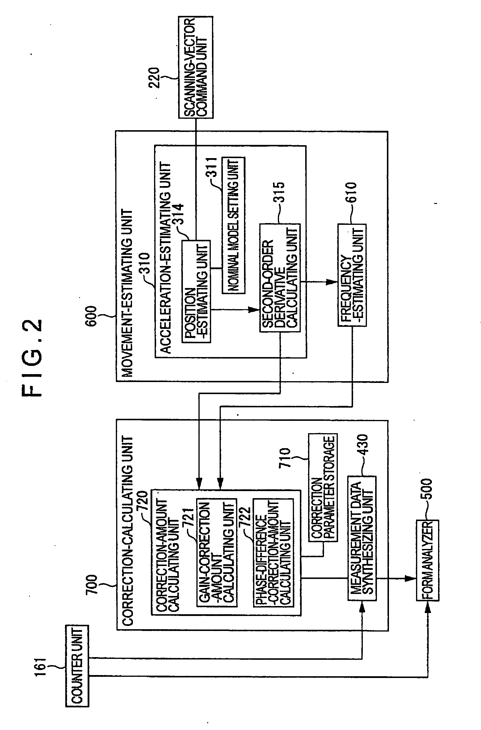
[0322]FIG. 18 is an illustration showing an arrangement of a movement-estimating unit, correction-calculating unit and an estimation-judging unit of the second embodiment.

[0323]The estimation-judging unit 800 includes: an actual acceleration calculating unit 810 for calculating an actual acceleration based on the measured value of the coordinates detected by the counter unit 161; a difference-calculating unit 820 that compares an estimated acceleration value calculated by the movement-estimating unit 600 to the actual acce...


PUM


Abstract

A surface-profile measuring instrument includes a movement-estimating unit (600) that estimates an movement state of a drive mechanism in accordance with a scanning vector command issued by a scanning vector commanding unit (220) to calculate an estimated movement state quantity, and a correction calculating unit (700) that corrects a detection value of a drive sensor in accordance with the estimated movement state quantity calculated by the movement estimating unit (600).
The movement-estimating unit (600) has a nominal model setting unit (311) in which a nominal model as a frequency transfer characteristics from the scanning vector commanding unit to the probe of the scanning probe is set. The correction-calculating unit (700) includes a correction-amount calculating unit (720) that calculates a correction amount for correcting a measurement error generated by a deformation of the drive mechanism in accordance with the movement thereof and a measurement data synthesizing unit (430) that synthesizes the detection value of the drive sensor and the displacement sensor and the calculated correction-amount calculated by the correction-amount calculating unit (720).

Description

BACKGROUND OF THE INVENTION[0001]1. Field of the Invention[0002]The present invention relates to a surface-profile measuring instrument[0003]More specifically, it relates to a surface-profile measuring instrument that scans a surface of a workpiece to measure a contour, surface roughness, waviness and the like of the workpiece.[0004]2. Description of Related Art[0005]A surface-profile measuring instrument that scans a surface of a workpiece to obtain a three-dimensional shape of the workpiece has been known[0006]FIG. 19 shows an arrangement of a measuring system 100 (surface-profile measuring instrument) using a scanning probe 130.[0007]The measuring system 100 includes a coordinate measuring machine 110 that moves scanning probe 130, a manually-operated console 150, a motion controller 160 for controlling the movement of the coordinate measuring machine 110 and a host computer 200 that drives the coordinate measuring machine 110 via the motion controller 160 and processes the measu...

Claims


Application Information

Patent Timeline
Patent Type & Authority Applications(United States)
IPC IPC(8): G06F19/00G01C25/00G01B5/20
CPCG01B21/045
Inventor ISHIKAWA, NOBUHIROKIYOTANI, SHINGO
Owner MITUTOYO CORP
Why Eureka
Try Eureka