Head with roller for pulse-echo ultrasonic inspection of parts in an automatic parts inspection facility

a technology of pulse echo and ultrasonic inspection, applied in the direction of instruments, magnetic properties, specific gravity measurements, etc., can solve the problem of not being head scanners, and achieve the effect of reducing the effect of mechanical til

Inactive Publication Date: 2008-03-20
AIRBUS OPERATIONS SL
View PDF10 Cites 23 Cited by
  • Summary
  • Abstract
  • Description
  • Claims
  • Application Information

AI Technical Summary

Benefits of technology

[0006]Each of the ends of the roller's stationary axis are connected to vertical connection means that are connected to the first frame by aligned lateral pivoting axis that allow a swiveling motion and are located in a lower plane than the stationary axis displacing the pivoting axis downwards, which position allows positioning the ultrasound scanner or scanners housed inside the roller perpendicular to the surface on which the roller rests. This perpendicular position is the optimum position for ultrasonic inspection. The means of vertical connection may be vertical clamps that have, each one, an upper part connected to an end of the respective stationary axis and a lower part connected to one of the pivoting axles, in such a manner that each pivot

Problems solved by technology

The automatic systems used to date for ultrasonic inspection use rigid or semi-rigid heads made by one or more scanners with coupling achieved by local immersion in the part to be inspected, being then appropriate for flat or semi flat parts, but having difficulty inspecting curved parts, since the rigid head could not adapt adequately to the variations of the surface to be inspected, and therefore, said rigid head could not keep contact with the s

Method used


Image

  • Head with roller for pulse-echo ultrasonic inspection of parts in an automatic parts inspection facility
  • Head with roller for pulse-echo ultrasonic inspection of parts in an automatic parts inspection facility
  • Head with roller for pulse-echo ultrasonic inspection of parts in an automatic parts inspection facility

Examples


Embodiment Construction

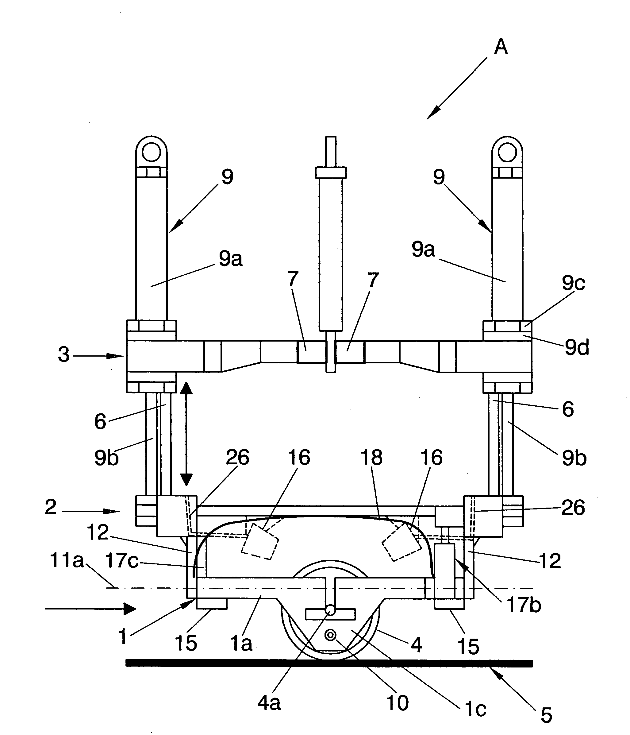
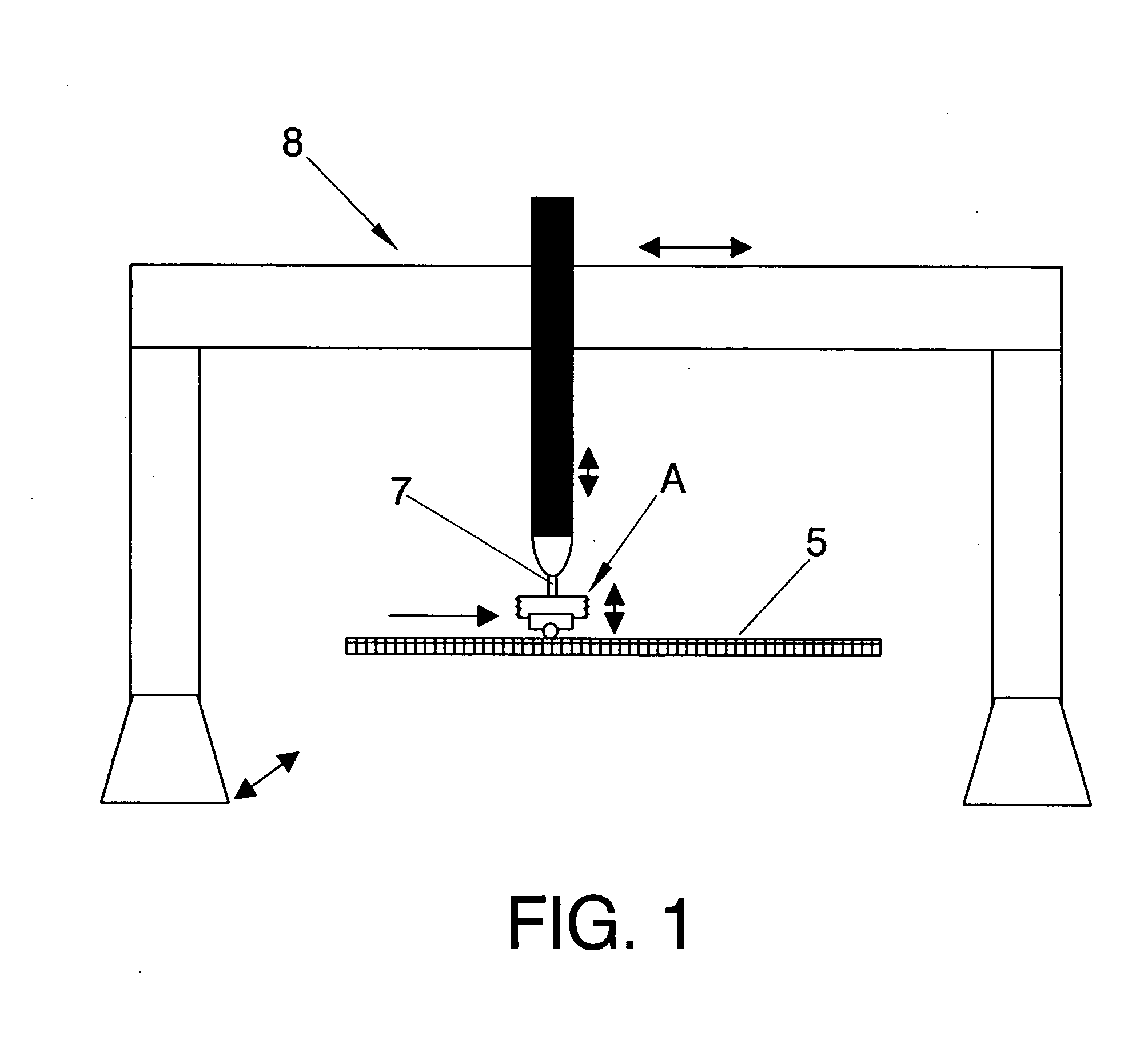
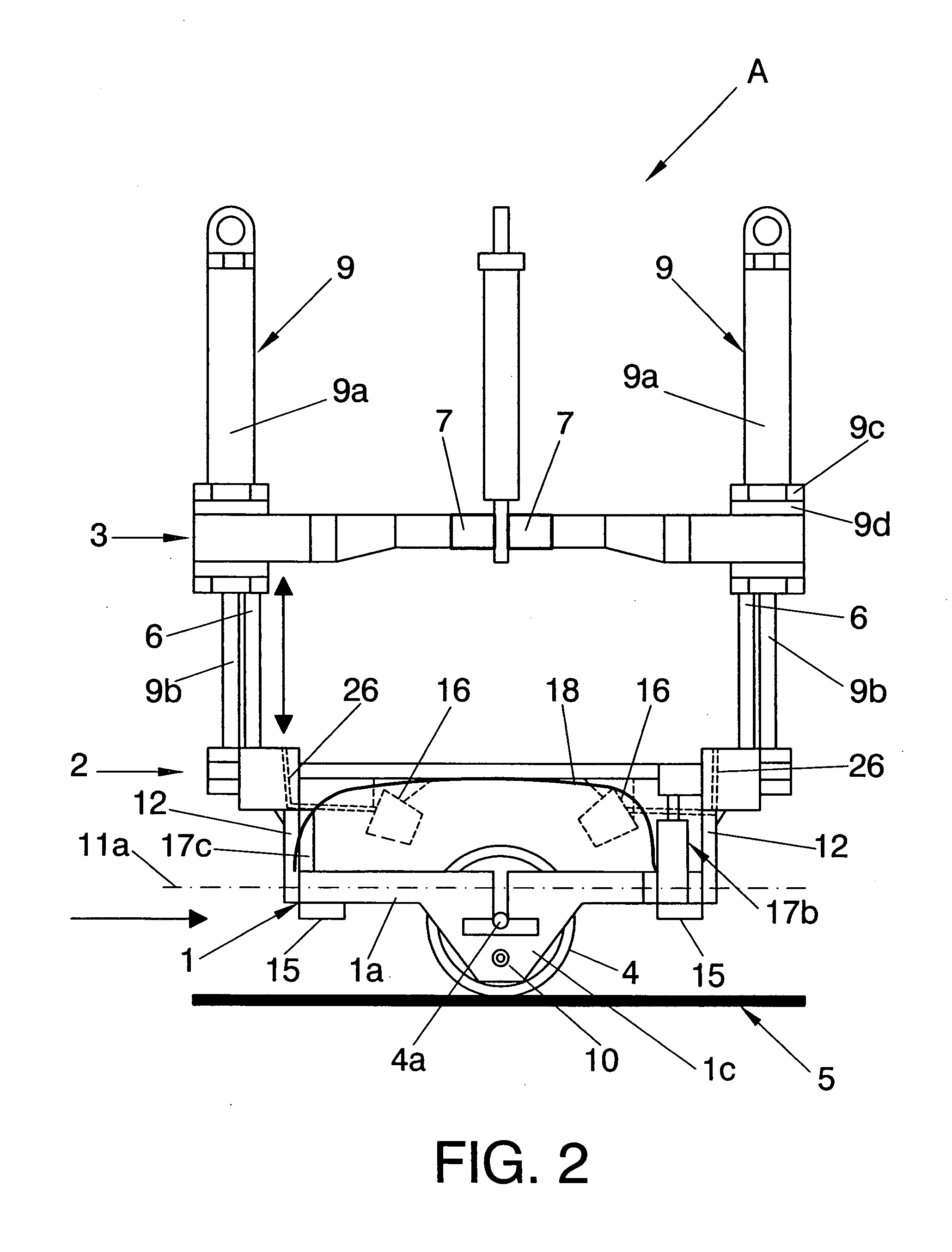
[0005]The object of the present invention is to overcome the current disadvantages of the art as specified above, by means of a head that includes, at least, a conventional or multielement (phased array) ultrasound scanner housed inside a roller capable of rolling over the surface of the part to effect the pulse echo ultrasonic inspection of carbon fiber parts, and that has a first frame in which the roller pivots around a stationary axis arranged perpendicularly to the direction in which the head moves, a second frame from which vertical linear guides emerge and that is connected to the first frame in a swiveling arrangement, a third frame, that slides vertically by means of the linear guides, and coupling means to couple the third frame to an automatic motion installation which probe has also the following characteristics.

[0006]Each of the ends of the roller's stationary axis are connected to vertical connection means that are connected to the first frame by aligned lateral pivoti...


PUM


Abstract

Head for ultrasonic inspection with a semidry coupling system involving a roller (4) and an ultrasound scanner that rolls on the surface (5) of the part to be inspected and that includes a first frame (1) to which the roller (4) is connected and pivots around an stationary axis (4a) in direction that is perpendicular to the probe's movement; a second frame (2) from which linear vertical guides (6) emerge and is connected in an oscillatory manner to the first frame (1) through an oscillating axis (11a) that is perpendicular to the stationary axis (4a): a third frame (3) that slides vertically through the linear guides (6); at least two actuators of the vertical adjustment (9) anchored to the third frame (3) and to the second frame (2); their corresponding laterally aligned pivotal axis (10), connected to the first frame (1) in a rotating manner and parallel to and lower from the plane of the stationary axis (4a) and the respective ends of the stationary axis (4a).

Description

TECHNICAL FIELD OF THE INVENTION[0001]The present invention falls within the technical field of non-destructive inspection of parts of composite materials by means of ultrasound techniques, and more particularly, the present invention refers to a head with roller for the ultrasonic inspection by pulse echo, that can be coupled to automatic inspection installations of parts manufactured from composite materials of large dimensions, particularly of parts used in the aeronautic industry.STATE OF THE PRIOR ART[0002]Ultrasonic inspection is today a process habitually used for the non-destructive inspections of parts made of carbon fiber. More particularly, the ultrasonic inspection technique by pulse echo is based in introducing elastic mechanical waves in the material to be inspected that then propagate and experience reflection, refraction, attenuation, diffraction, etc. The waves do not experience any of these phenomena in the presence of homogenous materials, while if the material sh...

Claims


Application Information

Patent Timeline
IPC IPC(8): G01N29/04
CPCG01N29/225G01N29/2493G01N2291/102G01N29/28G01N29/265G01N29/223G01N29/2487G10K11/004G01N2291/2638G01N2291/2694
Inventor ESPADA TEJEDOR, ALVARO
Owner AIRBUS OPERATIONS SL
Why Eureka
Try Eureka