Display device and method of driving the same

Inactive Publication Date: 2008-03-20
SEMICON ENERGY LAB CO LTD
View PDF14 Cites 219 Cited by
  • Summary
  • Abstract
  • Description
  • Claims
  • Application Information

AI Technical Summary

Benefits of technology

[0010]As described above, various methods have been studied to solve the motion blur of moving images in hold-type display devices. However, such methods does not give sufficient effects and reach the same moving image characteristics as that of impulse type display devices. In addition, in the method in which a black image is inserted to make pseudo impulse type display, more flickers are viewed. Undesirably, the black image insertion

Problems solved by technology

However, such methods does not give sufficient effects and reach the same moving image characteristics as that of impulse type display devices.
Undesirably, the black image insertion causes decrease of an average luminance of an image, and the power consumption is increased to provide the same level of luminanc

Method used


Image

  • Display device and method of driving the same
  • Display device and method of driving the same
  • Display device and method of driving the same

Examples


embodiment modes

[0277]Embodiment Modes of the present invention will now be described. However, the present invention can be carried out in many different modes. Note that it is easily understood by those skilled in the art that the present invention is not limited to the following description and various changes may be made in modes and details without departing from the spirit and the scope of the present invention. Therefore, the present invention should not be limited to the descriptions of the embodiment modes below in this specification.

embodiment mode 1

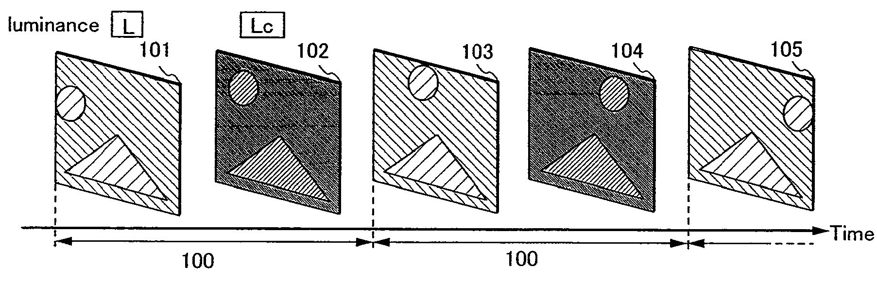
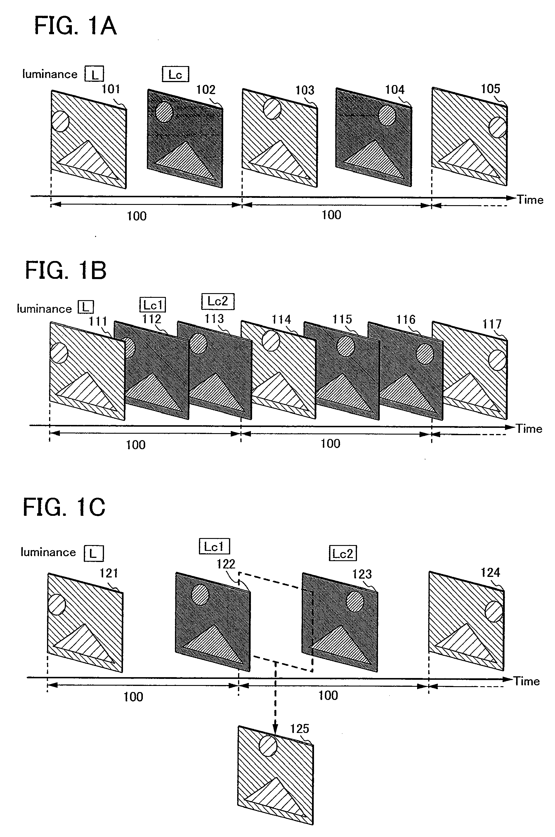
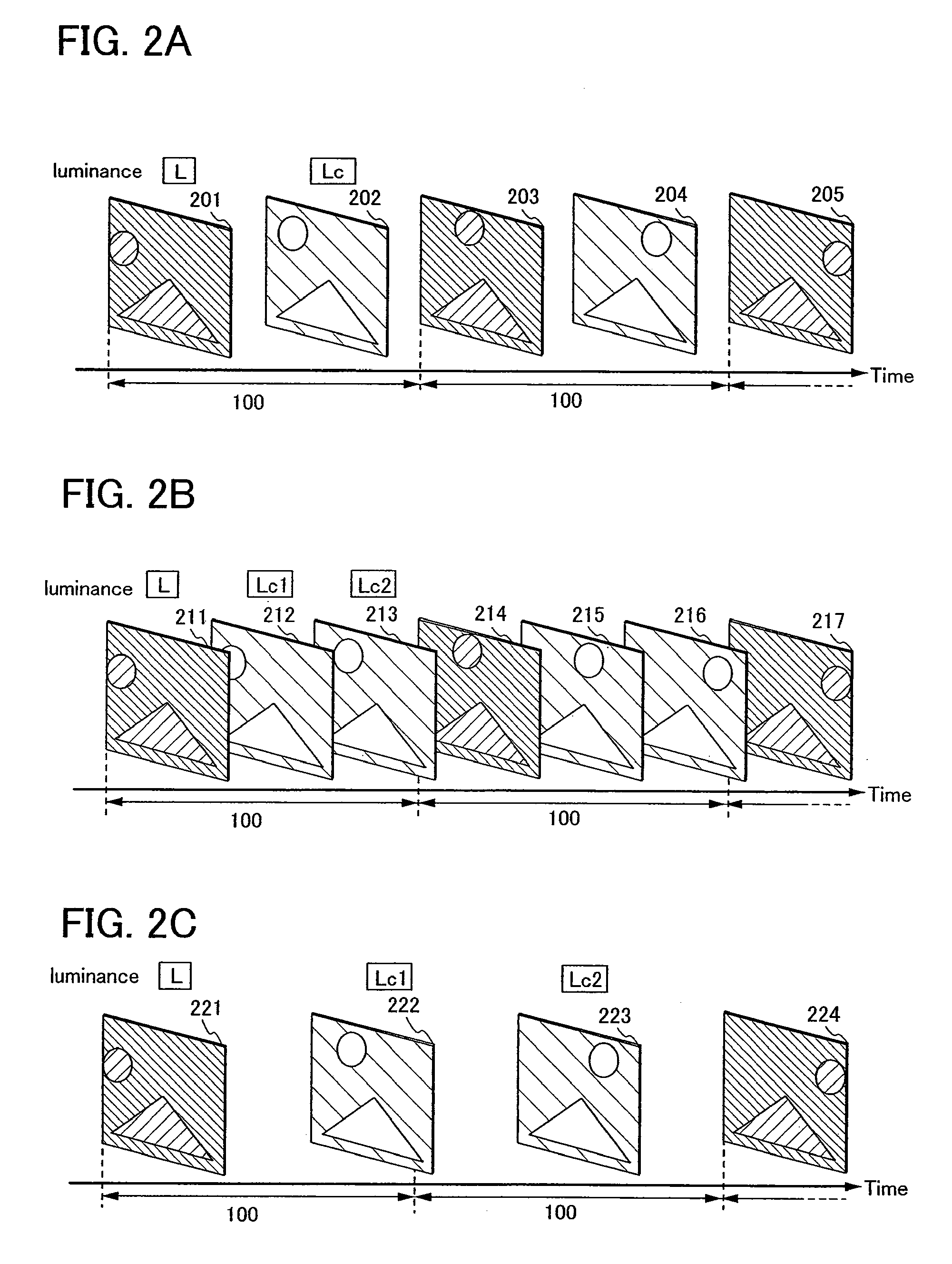
[0278]Embodiment Mode 1 will describe a method of driving a display device or a semiconductor device of this specification to reduce motion blur, as an example.

[0279]In this embodiment mode, a case is mainly described, in which, when a frame rate of an image data to be input (which is the number of frames per second and also referred to as a input frame rate) and a frame rate of display (also referred to as a display frame rate) are compared, the display frame rate is higher than the input frame rate. Specifically, while the input frame rate is 60 Hz, the display frame rate may be 90 Hz, 120 Hz, or 180 Hz. In addition, while the input frame rate is 50 Hz, the display frame rate is 75 Hz, 100 Hz, or 150 Hz. However, without limitations, various values may be adopted for the input frame rates and display frame rates.

[0280]When the input frame rate is higher than the display frame rate, a part of the image data to be input is abandoned so that the display frame rate can be satisfied. H...

embodiment mode 2

[0331]Embodiment Mode 2 will now describe a method of detecting movement of images in frames and making an intermediate image, and a method of controlling a driving method based on the movement of the images in frames or the like, by a driving method of a display device and a semiconductor device in this specification.

[0332]With reference to FIGS. 4A and 4B, a method in which the movement of images in frames is detected and an intermediate image is made is described. FIG. 4A illustrates a mode in which a display frame rate is twice as high as an input frame rate. FIG. 4A schematically illustrate the method in which the movement of an image is detected with time as a horizontal axis. The period 100 denotes one frame period. A first image 401 is a basic image of the previous frame, a second image 402 is an interpolation image, and a third image 403 is a basic image of the current frame. In the images, a first region 404, a second region 405 and a third region 406 are provided as regio...


PUM


Abstract

The present invention solves the motion blur of moving images in hold-type display devices. An amount of a moving image is detected from image data included in frames and an image at the intermediate state between an image of the current frame and an image of the next frame is made as an interpolation image. Thus, the movement of the image can follow the movement of human eyes and the luminance of the interpolation image is changed, and thus, display can be made close to pseudo impulse type display. In this manner, hold-type display devices without motion blur and methods of driving the hold-type display devices can be provided.

Description

BACKGROUND OF THE INVENTION[0001]1. Field of the Invention[0002]The present invention relates to display devices and methods of driving the display devices. Specifically, a method of improving the quality of moving images in the hold-type display devices.[0003]2. Description of the Related Art[0004]In recent years, there has been growing interests in thin display devices. As substitutes for CRT displays, liquid crystal displays, plasma displays, projection displays, and the like have been developed and becoming popular. Furthermore, field emission displays, inorganic electroluminescence displays, organic electroluminescence displays, electronic paper, and the like have been developed as next-generation display devices.[0005]In a display portion which is provided in the above-described display device, pixels which are minimum units for constituting an image are disposed. Each of the pixels emits light with certain luminance in accordance with the image data to display an image in the...

Claims


Application Information

Patent Timeline
IPC IPC(8): G09G5/00G09G3/36
CPCG09G3/2025H01L29/42384G09G3/325G09G3/3258G09G3/3406G09G3/3648G09G2300/0819G09G2300/0842G09G2300/0852G09G2300/0861G09G2310/024G09G2310/061G09G2310/08G09G2320/0252G09G2320/0261G09G2320/0271G09G2320/0276G09G2320/0626G09G2320/0673G09G2320/10G09G2320/106G09G2340/0435G09G2360/144G09G2360/18H01L27/1214G09G3/3233H01L27/124H01L27/1255G02F1/133G09G3/20G09G3/36G09G2320/02G09G2320/0233G09G2360/16
Inventor YOSHIDA, YASUNORIKIMURA, HAJIME
Owner SEMICON ENERGY LAB CO LTD
Why Eureka
Try Eureka