Optical scanner and image forming apparatus using optical scanner

an optical scanner and optical scanner technology, applied in the field of optical scanner and image forming apparatus, can solve the problems of optical properties, difference between magnification ratio change and magnification ratio chang

Active Publication Date: 2008-03-20
RICOH KK
View PDF23 Cites 55 Cited by
  • Summary
  • Abstract
  • Description
  • Claims
  • Application Information

AI Technical Summary

Benefits of technology

[0015] It is an object of the present invention to at least

Problems solved by technology

However, because a shape and a refractive index of the resin-made lens change due to the environmental fluctuations, especially due to temperature variation, the optical properties, especially a power, change from a designed value, and a “beam spot diameter” as a diameter of an optical spot on a scanned surface changes due to the environmental fluctuations.
When such reflected scattered light again returns to the semiconductor laser, the following problems arise.
However, a

Method used


Image

  • Optical scanner and image forming apparatus using optical scanner
  • Optical scanner and image forming apparatus using optical scanner
  • Optical scanner and image forming apparatus using optical scanner

Examples


Embodiment Construction

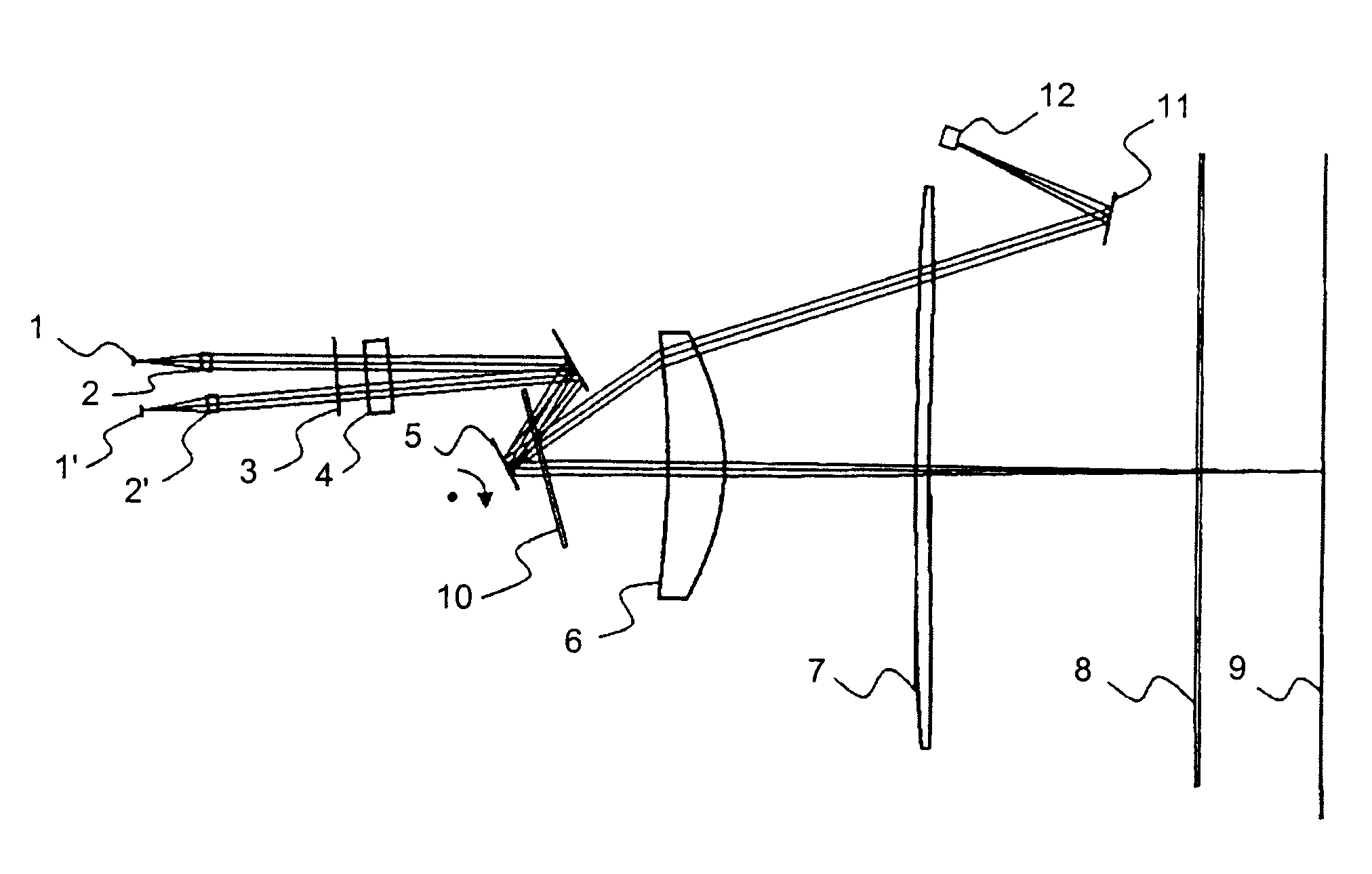
[0029]FIG. 1 is a schematic of a basic structure of an image forming apparatus according to the present invention.

[0030] In FIG. 1, optical sources (semiconductor lasers) are denoted by 1 and 1′, coupling lenses (first lenses) are denoted by 2 and 2′, a first aperture is denoted by 3, an anamorphic lens (second lens) is denoted by 4, a polygon mirror as a deflector is denoted by 5, a deflector-side scanning lens is denoted by 6, an image-surface-side scanning lens is denoted by 7, a dust-proof glass is denoted by 8, an image surface is denoted by 9, a soundproof glass is denoted by 10, a synchronization mirror is denoted by 11, and a synchronization detector (photo detector) is denoted by 12.

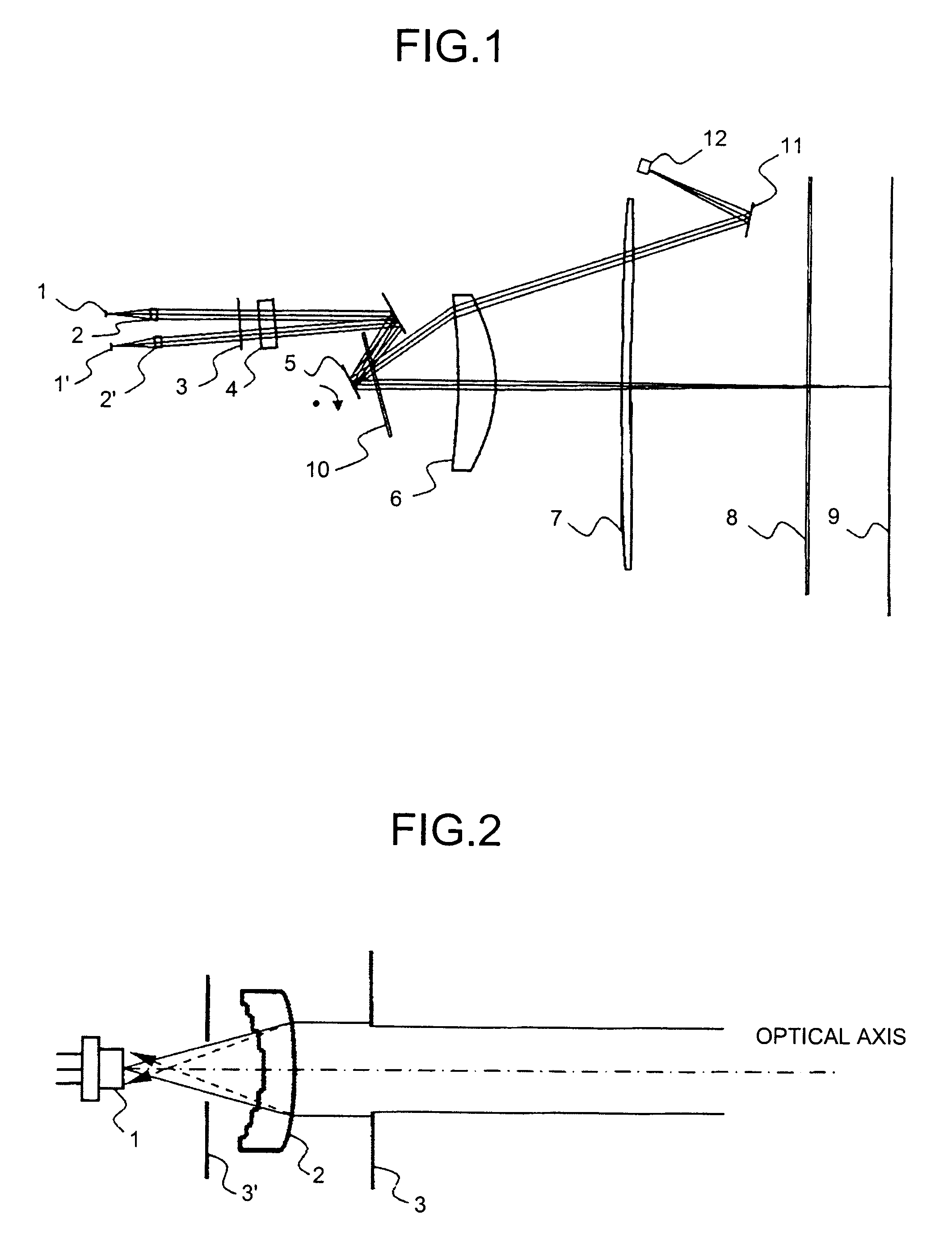
[0031] The optical source 1 is a semiconductor laser having a cover glass of 0.3 mm in thickness.

[0032] A light beam emitted from the optical source 1 becomes a parallel light, a weak divergent light, or a weak convergent light via the coupling lens 2 having a resin-made diffracting surface. ...


PUM


Abstract

An optical axis of at least one surface of a resin-made diffracting lens is shifted in a main scanning direction with respect to an incident beam. A synchronous detection can cancel a problem of a misalignment in the main scanning direction due to a temperature variation. A light reflected from a second surface of the resin-made diffractive lens condenses on a position that is displaced in an optical axis direction from an optical beam outgoing point of a semiconductor laser, and thereby the light reflected again from the semiconductor laser does not form an image on a scanned surface and an impact on the image becomes low.

Description

CROSS-REFERENCE TO RELATED APPLICATIONS [0001] The present application claims priority to and incorporates by reference the entire contents of Japanese priority document, 2006-253375 filed in Japan on Sep. 19, 2006. BACKGROUND OF THE INVENTION [0002] 1. Field of the Invention [0003] The present invention relates to an optical scanner and an image forming apparatus. [0004] 2. Description of the Related Art [0005] An optical scanner is widely used for an image forming apparatus such as an optical printer, a digital copier, and an optical plotter. Recently, the optical scanner has been required to be manufactured at low cost, to be unaffected by environmental fluctuations, and to form an image with high-resolution. [0006] When various lenses to be used in the optical scanner are made of a resin material, such a resin-made lens is light in weight, can be made at low cost, and have easiness in forming a particular surface shape typified by an aspherical surface. Therefore, an adoption of...

Claims


Application Information

Patent Timeline
IPC IPC(8): G02B26/10
CPCG02B27/40G02B26/127
Inventor HAYASHI, YOSHINORISAKAI, KOHJIUEDA, TAKESHIICHII, DAISUKESAISHO, KENICHIROH
Owner RICOH KK
Why Eureka
Try Eureka