Tape Path Control System With Precision-Aligned Conjugated Rollers

a control system and roller technology, applied in the direction of mechanical tension control of carriers, recording on magnetic tapes, instruments, etc., can solve the problems of poor data transfer reliability, low readback signal amplitude, and inability to handle transient lateral movements that are beyond the servo response capabilities of systems

Inactive Publication Date: 2008-03-20
IBM CORP
View PDF30 Cites 17 Cited by
  • Summary
  • Abstract
  • Description
  • Claims
  • Application Information

AI Technical Summary

Benefits of technology

[0011]The foregoing problems are solved and an advance in the art is obtained by a tape path control system and related method for controlling the position of a tape medium in the tape drive. The tape path includes a first tape guide roller, a second tape guide roller spaced from the first roller, and a transducing head situated between the first and second rollers. The first and second rollers may be large and closely spaced, with the second tape guide roller being spaced from the first roller at a roller diameter / center-to-center spacing ratio of between approximately 1:1-1:2 while still accommodating the transducing head therebetween. The transducing head may be positioned to lie on an opposite side of the tape medium from the first and second guide rollers, or on the same side of the tape. A precision alignment system is associated with the second roller. When operable, the precision alignment system allows the second roller to be adjustably aligned relative to the first roller in order to control lateral tape movement when a tape medium streams across the rollers in operative engagement with the transducing head.
[0012]The precision alignment system may include an axial adjustment control adapted to adjust a position of the second roller along an axis thereof. The axial adjustment control may engage the base end of a bearing shaft on the second roller, such as by way of a set screw that is adjustably threaded or otherwise adjustably mounted relative to a fixed reference structure. The set screw may be axially aligned with the bearing shaft and may engage an end face of the bearing shaft, such that the second roller is tiltable about the set screw.
[0013]The precision alignment system may further include a tilt angle adjustment control adapted to adjust a tilt angle of the second roller. The tilt angle adjustment control may engage a free terminal end of a bearing shaft on the second roller, with a base end of the bearing shaft being pivotally mounted. The tilt angle adjustment control may include one or more set screws that are adjustably threaded or otherwise adjustably mounted relative to a fixed reference structure, with the set screw(s) being aligned to engage a side portion of the bearing shaft's free terminal end. The one or more set screws may extend parallel or perpendicular to the bearing shaft and may have tapered or flat ends that adjustably engage the side of the bearing shaft according to a set screw adjustment position.
[0014]According to the inventive method, the second roller may be adjustably aligned relative to the first roller in order to control lateral tape movement when a tape medium streams across the rollers in operative engagement with the transducing head. A precision alignment system may be used to provide the desired adjustments. Once the required adjustments are made, the second roller may be permanently fixed in the alignment position or may remain dynamically adjustable during use.

Problems solved by technology

This can produce low readback signal amplitude and poor data transfer reliability.
Although the tape drive servo actuation system “SAS” is capable of compensating for some lateral tape motion, it cannot handle transient lateral movements that are beyond the servo response capabilities of the system.
That is to say, there are some lateral transients that are simply too fast or too large for the servo actuation system “SAS,” such that data read / write errors cannot be avoided.

Method used


Image

  • Tape Path Control System With Precision-Aligned Conjugated Rollers
  • Tape Path Control System With Precision-Aligned Conjugated Rollers
  • Tape Path Control System With Precision-Aligned Conjugated Rollers

Examples


Embodiment Construction

[0031]The invention will now be described by way of exemplary embodiments shown by the drawing figures (which are not necessarily to scale), in which like reference numerals indicate like elements in all of the several views.

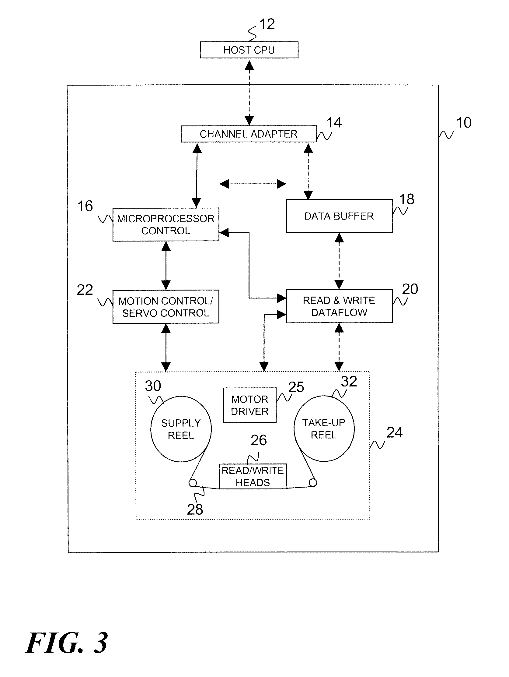
[0032]Turning to FIG. 3, the inventive concepts herein described may be embodied in a tape drive data storage device (tape drive) 10 for storing and retrieving data by a host data processing device 12, which could be a general purpose computer of other processing apparatus adapted for data exchange with the tape drive 10. The tape drive 10 includes plural components providing a control and data transfer system for reading and writing host data on a magnetic tape medium. By way of example only, those components may conventionally include a channel adapter 14, a microprocessor controller 16, a data buffer 18, a read / write data flow circuit 20, a motion control system 22, and a tape interface system 24 that includes a motor driver circuit 25 and a read / write head u...


PUM

PropertyMeasurementUnit
diameteraaaaaaaaaa
diameteraaaaaaaaaa
diameteraaaaaaaaaa

Abstract

A tape path control system and related method for controlling the position of a tape medium in the tape drive. The tape path includes a first tape guide roller, a second tape guide roller spaced from the first roller, and a transducing head situated between the first and second rollers. The first and second rollers may be large and closely spaced, with the second tape guide roller being spaced from the first roller at a roller diameter/center-to-center spacing ratio of between approximately 1:1-1:2 while still accommodating the transducing head therebetween. The transducing head may be positioned to lie on an opposite side of the tape medium from the first and second guide rollers, or on the same side of the tape. A precision alignment system is associated with the second roller. When operable, the precision alignment system allows the second roller to be adjustably aligned relative to the first roller in order to control lateral tape movement when a tape medium streams across the rollers in operative engagement with the transducing head. The precision alignment system may include an axial adjustment control adapted to adjust a position of the second roller along an axis thereof. The precision alignment system may further include a tilt angle adjustment control adapted to adjust a tilt angle of the second roller.

Description

BACKGROUND OF THE INVENTION[0001]1. Field of the Invention[0002]This invention relates to tape drive data storage systems. More particularly, the invention is directed to controlling the path of a streaming tape medium relative to the tape drive transducing elements that read and write data on the tape.[0003]2. Description of the Prior Art[0004]By way of background, during the operation of a tape drive data storage apparatus, a tape medium is transferred back and forth between supply and take-up reels while data is read from or written to tape by one or more read / write heads. Typically, the tape medium and the supply reel are mounted inside a tape cartridge that is inserted into a slot in the tape drive. When the tape cartridge is situated in its operational position within the slot, a tape feed mechanism advances the tape onto the take up reel (which is typically within the tape drive) and into registered engagement with the read / write heads. The tape is then advanced past the read...

Claims


Application Information

Patent Timeline
Patent Type & Authority Applications(United States)
IPC IPC(8): G11B15/60
CPCG11B5/584G11B15/602G11B15/43
Inventor BISKEBORN, ROBERT G.IMAINO, WAYNE I.
Owner IBM CORP
Why Eureka
Try Eureka