Image stabilizing system and optical apparatus

Active Publication Date: 2008-03-20
CANON KK
View PDF3 Cites 30 Cited by
  • Summary
  • Abstract
  • Description
  • Claims
  • Application Information

AI Technical Summary

Problems solved by technology

In other words, a shift shake cannot be corrected until the camera is focused on the object.
However, in the case of a large hand motion, the focus precision becomes deteriorated.
This not only makes it difficu

Method used


Image

  • Image stabilizing system and optical apparatus
  • Image stabilizing system and optical apparatus
  • Image stabilizing system and optical apparatus

Examples


first embodiment

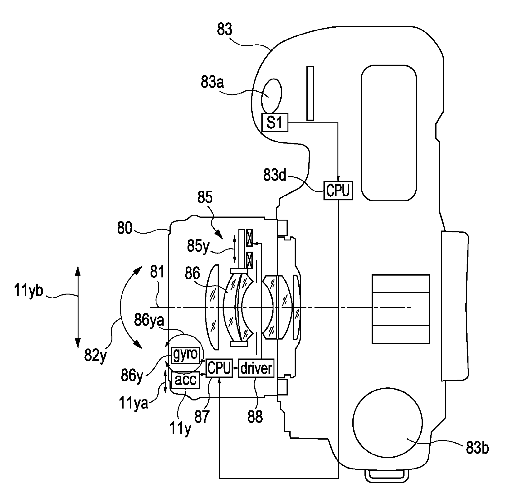
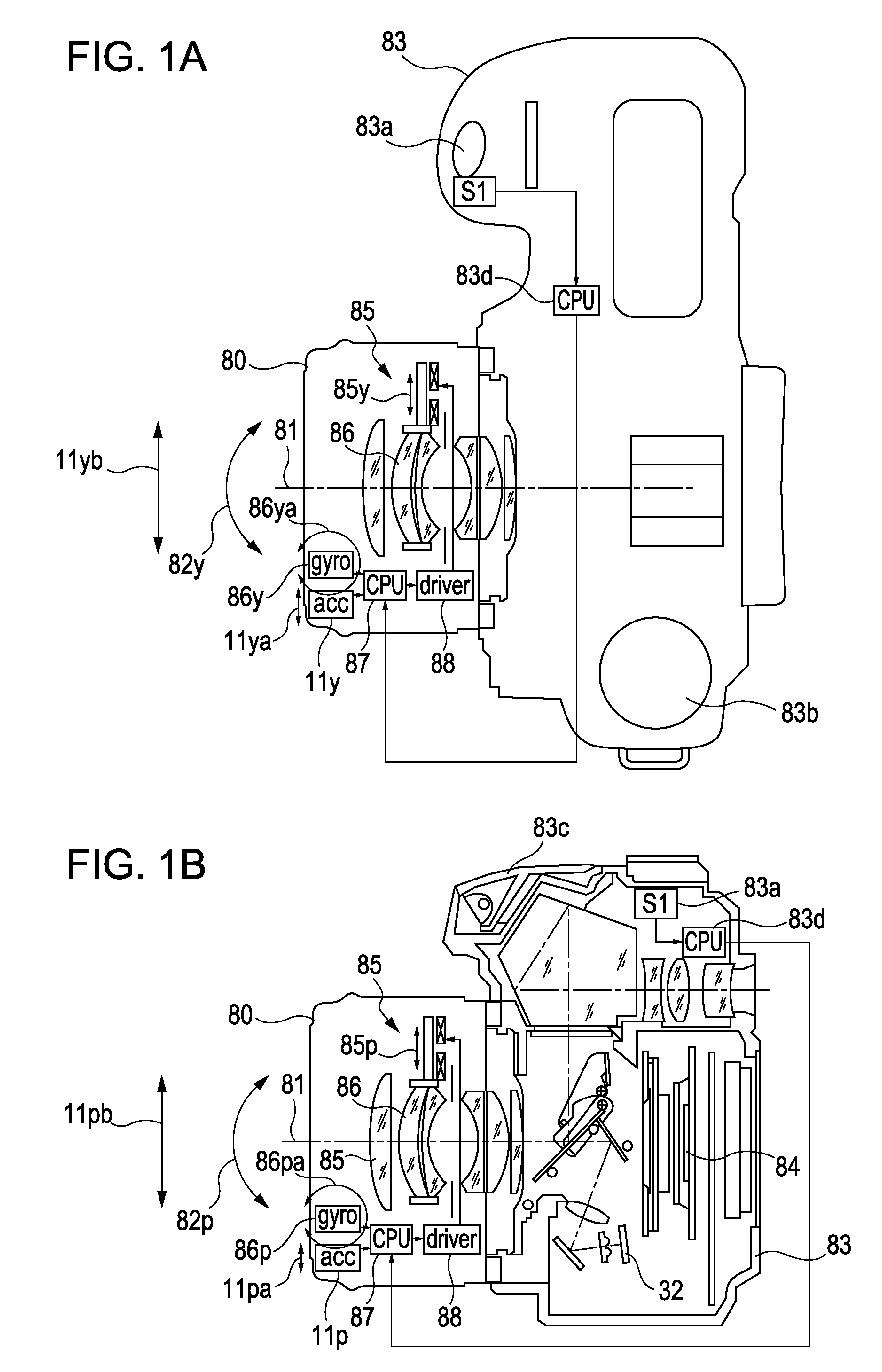
[0032]FIGS. 1A and 1B are a cross-sectional plan view and a cross-sectional side view of a single-lens reflex camera according to a first embodiment of the present invention. The single-lens reflex camera of the first embodiment of the invention differs from that of the related art shown in FIGS. 9A and 9B in having accelerometers 11p and 11y. The acceleration detection axes of the accelerometers 11p and 11y are aligned with the arrows 11pa and 11ya shown in FIGS. 1A and 1B. The arrows 11pb and 11yb indicate shift shake in the corresponding directions.

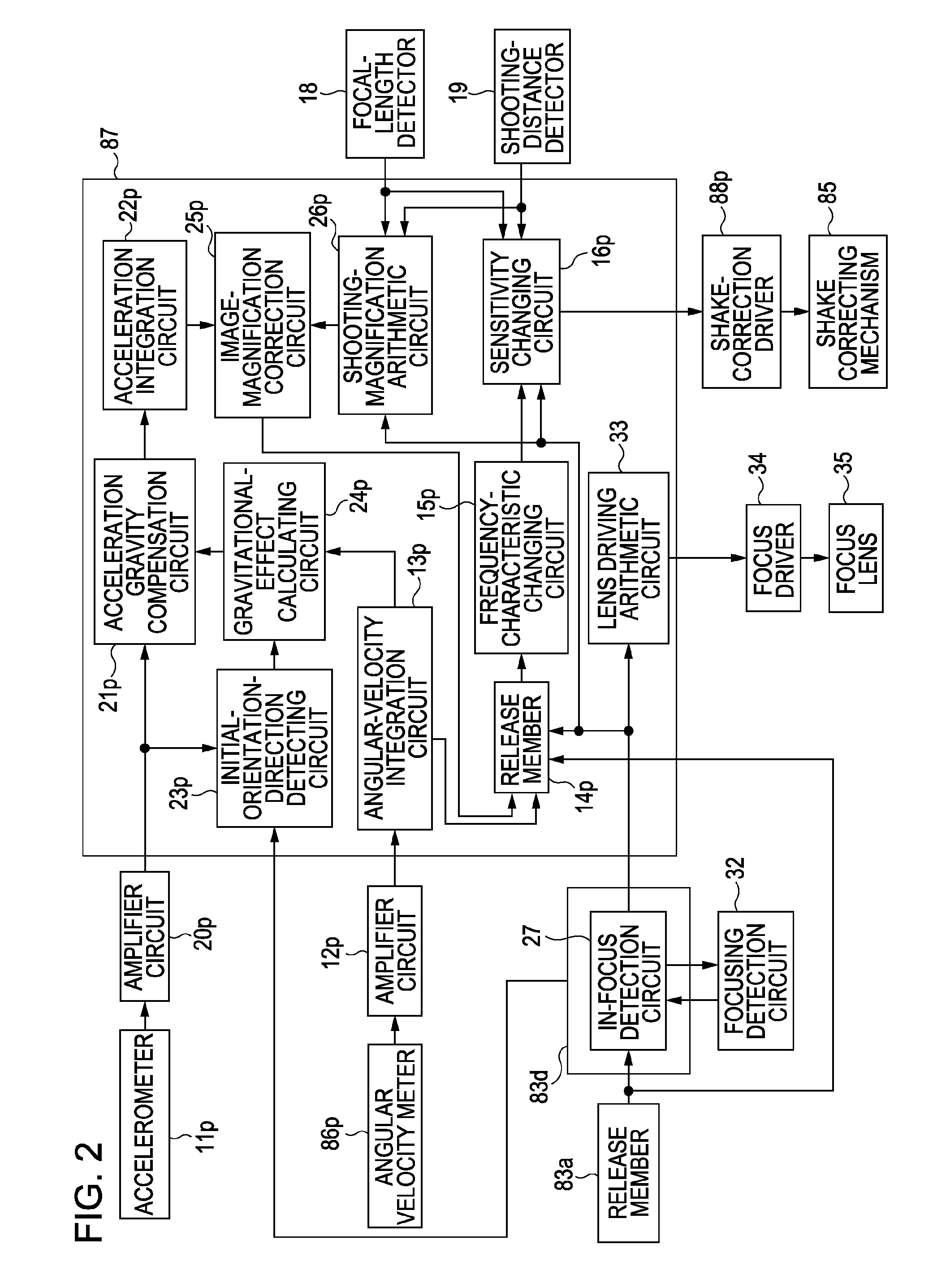
[0033]FIG. 2 is a block diagram that includes a circuit that processes signals of shift shake detected by the accelerometers 11p and 11y and signals of rotational shake detected by angular velocity meters 86p and 86y. The processing of these signals is implemented within a lens microcomputer (CPU) 87. FIG. 2 only shows signal processing for alleviating image shake caused by pitch shake of the camera (i.e. rotational shake corresponding...

second embodiment

[0080]A single-lens reflex camera according to a second embodiment of the present invention will now be described. The second embodiment differs from the first embodiment in FIG. 5 in that the rotational shake correction is started upon half-pressing of the release member 83a, that is, when the switch S1 is turned on, and that the shift shake correction is performed in an exposure process (when the release member 83a is fully pressed, that is, when a switch S2 is turned on). Other mechanical and electrical configurations of the camera in the second embodiment are the same as those in the first embodiment.

[0081]FIG. 6 is a flow chart of an operation for performing image-shake correction according to the second embodiment of the present invention. This operation starts when the main power switch of the camera is turned on. The steps performed in this operation that correspond to those in the operation of the first embodiment shown in FIG. 5 are given the same step numbers. Similar to ...

third embodiment

[0090]A single-lens reflex camera according to a third embodiment of the present invention will now be described. The third embodiment differs from the second embodiment in that the rotational shake correction is started when the main power switch of the camera is turned on (that is, in response to activation of the camera), and that the shift shake correction is performed upon half-pressing of the release member 83a, that is, when the switch S1 is turned on. Other mechanical and electrical configurations of the camera in the third embodiment are the same as those in the first and second embodiments.

[0091]FIG. 7 is a flow chart of an operation for performing image-shake correction according to the third embodiment of the present invention. This operation starts when the main power switch of the camera is turned on. The steps performed in this operation that correspond to those in the operations of the first and second embodiments shown in FIGS. 5 and 6 are given the same step number...


PUM


Abstract

An image stabilizing system performs rotational-shake correction to increase focus precision so that shift shake correction can be performed with high precision based on highly accurate image magnification information obtained by the high focus precision. The image stabilizing system includes a rotational-shake detecting unit that detects rotational shake occurring around a shooting light axis of an optical apparatus; a parallel-shake detecting unit that detects parallel shake occurring within a plane orthogonal to the light axis; a shake correcting unit that reduces image deterioration caused by the rotational shake and parallel shake; and an image stabilizing unit that actuates the shake correcting unit at an initial stage of a shake correcting process based on an output signal from the rotational-shake detecting unit, and actuates the shake correcting unit at a subsequent stage of the shake correcting process based on output signals from the rotational-shake detecting unit and the parallel-shake detecting unit.

Description

BACKGROUND OF THE INVENTION[0001]1. Field of the Invention[0002]The present invention relates to image stabilizing systems having shake correcting units for correcting image shake caused by, for example, hand motion, and to optical apparatuses equipped with such image stabilizing systems.[0003]2. Description of the Related Art[0004]In recent cameras, the basic operations involved in performing a photographing operation, such as exposure setting and focusing, are completely automated. Therefore, even those unaccustomed to operating cameras are less likely to fail in taking a picture. Furthermore, in recent years, there has been researched a system for preventing image shake caused by hand motion. For these reasons, the user rarely fails in taking a satisfactory picture.[0005]Such an image-shake preventing system will be described briefly below.[0006]Hand motion occurring when taking a picture with a camera is normally a vibration with a frequency of 1 Hz to 10 Hz. When hand motion oc...

Claims


Application Information

Patent Timeline
IPC IPC(8): G03B17/00
CPCG03B5/00
Inventor WASHISU, KOICHI
Owner CANON KK
Why Eureka
Try Eureka