
Substrate container opener and opener-side door drive mechanism thereof

Active Publication Date: 2008-03-20
KAWASAKI HEAVY IND LTD
View PDF11 Cites 10 Cited by
  • Summary
  • Abstract
  • Description
  • Claims
  • Application Information

AI Technical Summary

Benefits of technology

[0026] As mentioned above, according to the present invention, with the movement of the movable body, in the forward and backward directions X due to the movable body drive means, the container-side door held by the opener-side door can be moved both in the forward and backward directions X and in the direction vertical to the forward and backward directions X. Thus, the container-side door can be moved close to or away from the container main body so as to open and close the container main body. It is noted that the forward and backward directions X in which the movable body is moved are those parallel to the front face direction in which the space for containing substrates is opened, with respect to the container main body supported by the container supporting portion. In this case, the movable body can be moved in the forward and backward directions X while being located in the vicinity of the substrate container supported by the container supporting portion. Therefore, there is no need for providing a mechanism for moving the movable body in a region spaced away from the container supporting portion. Accordingly, in the present invention, the opener-side door drive mechanism can be located in the vicinity of the container supporting portion, thereby to downsize the substrate container opener. In addition, a space provided away from the container supporting portion for supporting the substrate container in the substrate container opener can be utilized effectively.
[0058] As mentioned above, according to the present invention, since the substrate container opener having the opener-side door drive mechanism described above is mounted on the substrate transfer apparatus, downsizing due to the downsizing of the substrate container opener can be realized. In addition, a space provided away from the container supporting portion in the direction vertical to the forward and backward directions X can be utilized effectively.

Problems solved by technology

In addition, the space below the FOUP supporting portion 11 can not be utilized effectively.
Such problems also occur, in the same manner, in a substrate container opener in which substrates other than semiconductor wafers are contained.

Method used


Image

  • Substrate container opener and opener-side door drive mechanism thereof
  • Substrate container opener and opener-side door drive mechanism thereof
  • Substrate container opener and opener-side door drive mechanism thereof

Examples


Embodiment Construction

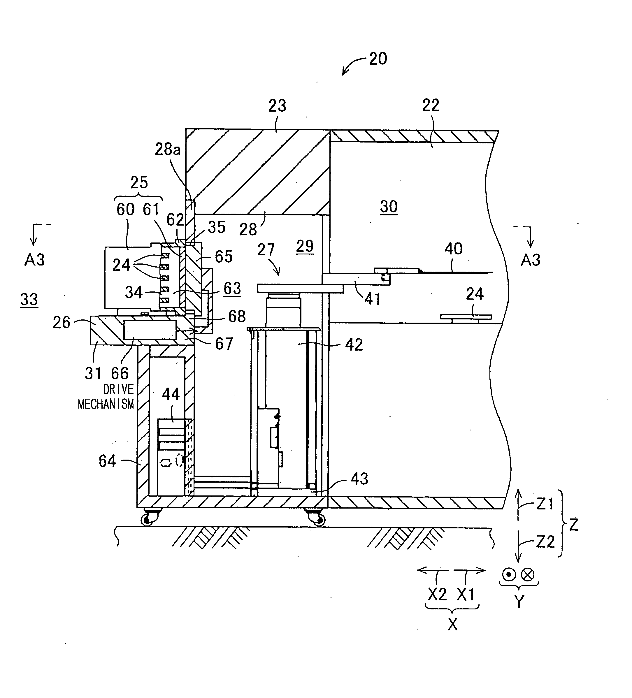
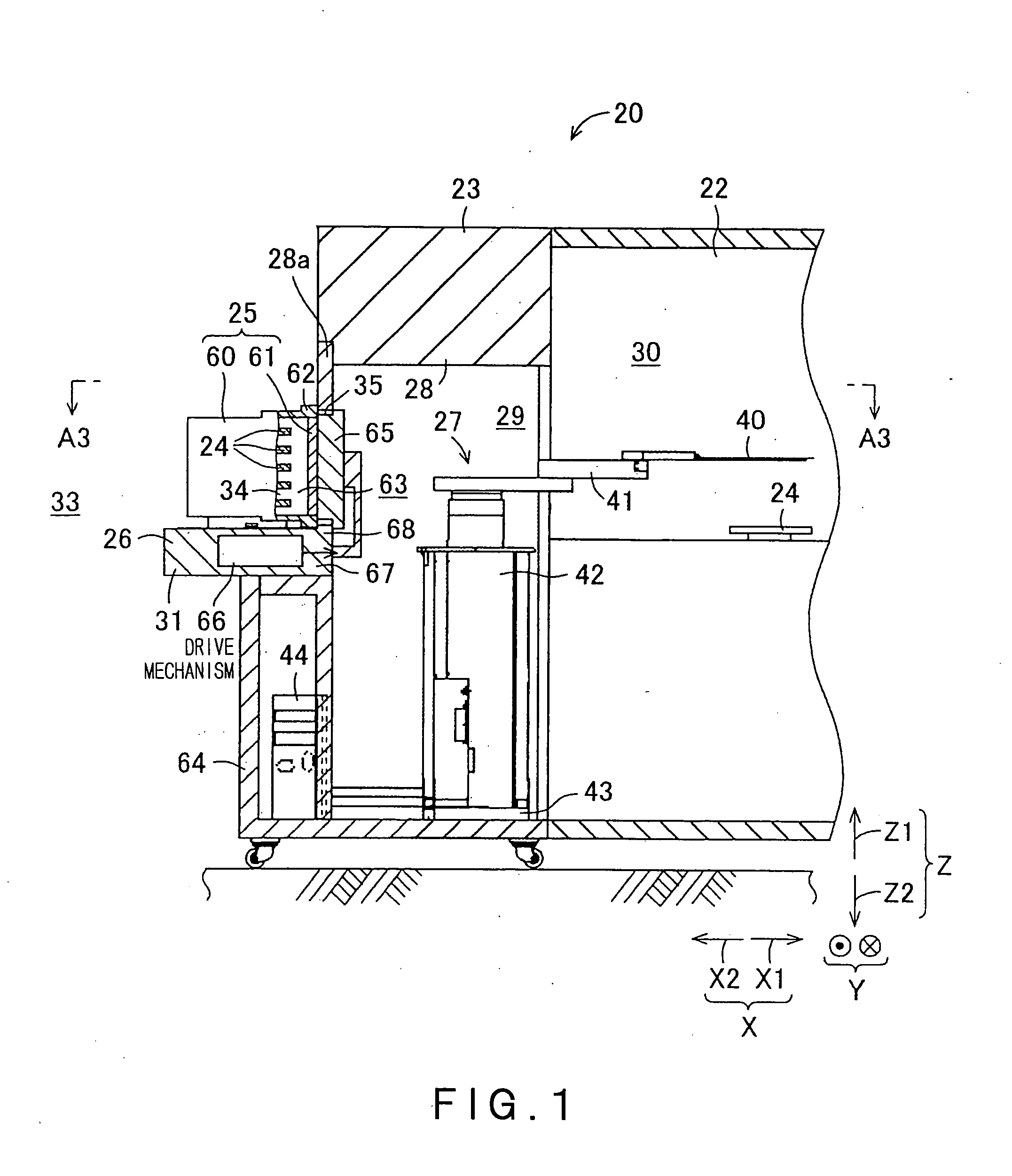
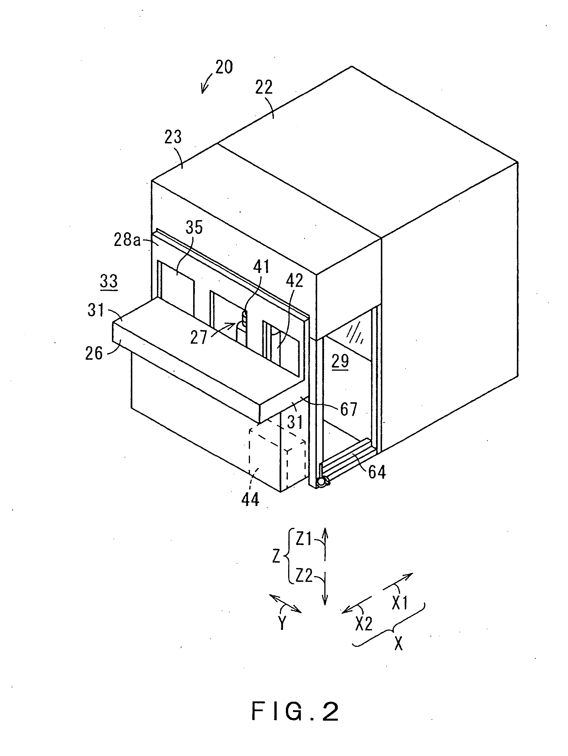
[0081] Referring to FIGS. 1 to 4, the semiconductor processing equipment 20 provides a predetermined process to each semiconductor wafer 24 which is a substrate to be processed. For example, as the process to be provided to the semiconductor wafer 24, various processes, including heating, impurity doping, film forming, lithography, washing or flattening may be included. The semiconductor processing equipment 20 performs the aforementioned processes in a processing space 30 filled with a predetermined atmospheric gas having adequate cleanliness. Wafers 24 are carried into the semiconductor processing equipment 20 while being contained in large numbers in a substrate container 25 referred to as a front opening unified pod (FOUP) 25.

[0082] As shown in FIG. 4, the FOUP 25 is configured to include a FOUP main body 60, which is a container main body in which the wafers 24 are contained, and a FOUP-side door 61 as a container-side door which can be attached to and detached from the FOUP m...


PUM


Abstract

In this invention, a movable body movable in forward and backward directions and a connector fixed to an opener-side door are connected with each other by link members so as to constitute a parallel link mechanism, such that they can be angularly displaced relative to each other. Link member angular displacement means controls the angular displacement of each link member relative to the movable body to be in a predetermined angular position, corresponding to the position of the movable body along the forward and backward directions. Reciprocation of the movable body in the forward and backward directions by movable body drive means moves the opener-side door in the forward and backward directions as well as in the upward and downward directions, thereby opening an opener-side opening. Since the movable body is moved only in the forward and backward directions, and necessity of moving and guiding the movable body in the upward and downward directions can be eliminated, the substrate container opener can be downsized, and a space provided below a FOUP supporting portion can be utilized effectively.

Description

CROSS REFERENCE TO RELATED APPLICATIONS [0001] This application is based upon the prior Japanese Patent Application No. 2006-228361 filed on Aug. 24, 2006, the entire contents of which are incorporated herein by reference. BACKGROUND OF THE INVENTION [0002] 1. Field of the Invention [0003] The present invention relates to a part of a substrate transfer apparatus for carrying in and carrying out a substrate in a substrate processing equipment, and particularly to an equipment front end module (EFEM) which is a substrate transfer apparatus of semiconductor processing equipment. [0004] 2. Background Art [0005]FIG. 20 is a section showing a semiconductor processing equipment 1 of a related art, which is partly cut away. The semiconductor processing equipment 1 is configured to include a wafer processing apparatus 2 and a wafer transfer apparatus 3. A space defined in the semiconductor processing equipment 1 is filled with a predetermined atmospheric gas. In this manner, attachment of du...

Claims


Application Information

Patent Timeline
IPC IPC(8): H01L21/677
CPCH01L21/67772Y10S414/139H01L21/67H01L21/68
Inventor HASHIMOTO, YASUHIKOTAKATORI, MASAO
Owner KAWASAKI HEAVY IND LTD
Learn More