Drill-in fluids and associated methods

Inactive Publication Date: 2008-03-20
HALLIBURTON ENERGY SERVICES INC
View PDF98 Cites 70 Cited by
  • Summary
  • Abstract
  • Description
  • Claims
  • Application Information

AI Technical Summary

Benefits of technology

[0009]In one embodiment, the present invention provides a method comprising: providing a drill-in fluid that comprises an aqueous base fluid, a viscosifier, a relative permeability modifier fluid loss control additive, and a degradable bridging agent comprising a degradable material capable of undergoing an irreversible degradation downhole; placing the drill-in fluid in a subterranean formation; and allowing the relative permeability modifier fluid loss control additive to reduce fluid loss from the drill-in

Problems solved by technology

Although this type of completion allows the produced fluids to flow directly into the well bore, it suffers the disadvantage that the sandface is unsupported and may collapse.
Also, selective treatments or remedial operations within the reservoir section may be more difficult.
However, degrading the filter cake may be difficult since the screen and gravel pack tend to prevent the components designed to degrade the filter cake from interacting with it.
Degrading the filter cake may be even more difficult, considering that the degradation is generally best when it is uniformly accomplished along what may be thousands of feet of open hole.
These delayed-release acid systems, however, can be problematic if they degrade the acid-soluble component of the filter cake too slowly or too quickly.
Removal of only 1% to 2% of the bridging solids in the filter cake can result in a significant loss of fluid to the surrounding formation.
This is undesirable.
On the other hand, if a delayed-release acid system is designed to totally degrade the acid-soluble portion within an acceptable “total cleanup time” (e.g., 24 to 48 hours), it is likely to cause hole instability and potential fluid loss problems

Method used


Image

  • Drill-in fluids and associated methods
  • Drill-in fluids and associated methods

Examples


examples

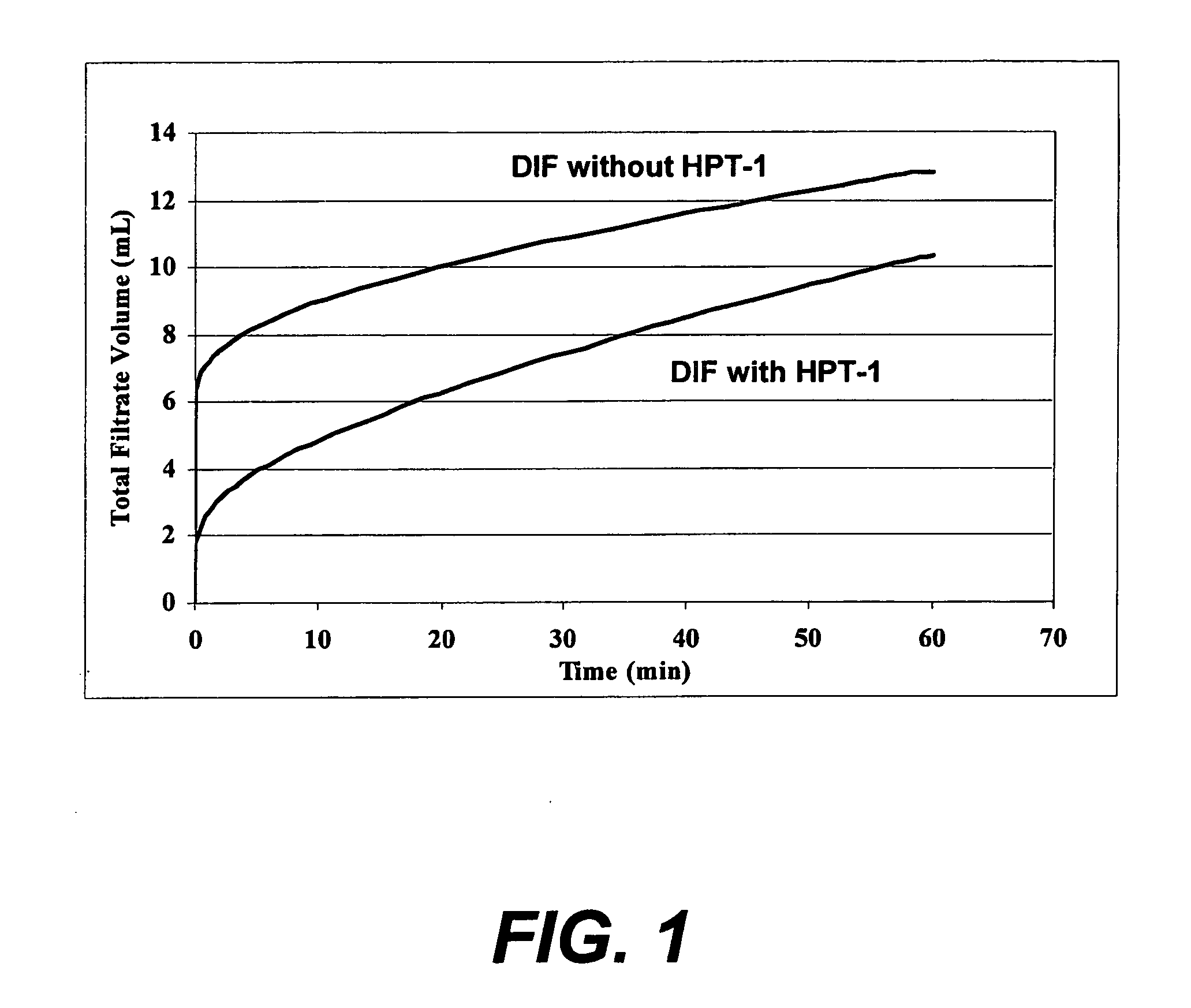
[0060]The drill-in fluids were made using a standard mud mixing and conditioning procedures. Tables 1 and list the components for each sample. “N-Vis” is a xanthan, and is available from Halliburton Energy Services, Duncan, Okla. “N-Dril HT Plus” is a starch, and is available from Halliburton Energy Services, Duncan, Okla. “Baracarb-50” is a calcium carbonate based bridging agent, and is available from Halliburton Energy Services, Duncan, Okla. “Baracarb-5” is a calcium carbonate bridging agent bridging agent, and is available from Halliburton Energy Services, Duncan, Okla. “HPT-1” is a relative permeability modifier fluid loss control additive, and is available from Halliburton Energy Services, Duncan, Okla. The water, salt, xanthan, and starch were mixed on a Hamilton-Beach blender at high speed for 20 minutes. The remaining ingredients were added at low speed and mixed for an additional five minutes. The mud samples were placed in sealed jars, and then in a 65° C. roller oven for...


PUM

PropertyMeasurementUnit
Fractionaaaaaaaaaa
Lengthaaaaaaaaaa
Timeaaaaaaaaaa

Abstract

Of the many methods provided herein, the present invention provides a method comprising: providing a drill-in fluid that comprises an aqueous base fluid, a viscosifier, a relative permeability modifier fluid loss control additive, and a degradable bridging agent comprising a degradable material capable of undergoing an irreversible degradation downhole; placing the drill-in fluid in a subterranean formation; and allowing the relative permeability modifier fluid loss control additive to reduce fluid loss from the drill-in fluid to the subterranean formation. Another example is a method of degrading a filter cake in a subterranean formation comprising: providing a filter cake produced by a drill-in fluid that comprises an aqueous base fluid, a viscosifier, a relative permeability modifier fluid loss control additive, and a degradable bridging agent comprising a degradable material capable of undergoing an irreversible degradation downhole; and allowing the degradable bridging agent to degrade.

Description

BACKGROUND OF THE INVENTION[0001]The present invention relates to fluid loss control for drill-in fluids for use in subterranean formations, and more particularly to fluid loss control for drill-in fluids and filter cakes comprising degradable bridging agents, and to methods of using such fluids in subterranean drilling operations.[0002]Many oil and gas wells in unconsolidated or poorly consolidated sandstone formations are completed “open hole,” meaning that the well bores do not contain casing or liners. Although this type of completion allows the produced fluids to flow directly into the well bore, it suffers the disadvantage that the sandface is unsupported and may collapse. Also, selective treatments or remedial operations within the reservoir section may be more difficult.[0003]Unconsolidated or poorly consolidated formations generally are high permeability production intervals and are drilled with specialized fluids referred to in the art as “drill-in fluids.” A drill-in flui...

Claims


Application Information

Patent Timeline
IPC IPC(8): C09K8/08
CPCC09K2208/18C09K8/5086
Inventor MUNOZ, TRINIDADEOFF, LARRY S.
Owner HALLIBURTON ENERGY SERVICES INC
Why Eureka
Try Eureka